When a tested brake was bedded, water spray was applied to carry on the braking test. A water spray device was installed right above engaging position between disc and pad, as illustrated in Fig.2. Water was supplied from a tap by pushing through a shower head onto
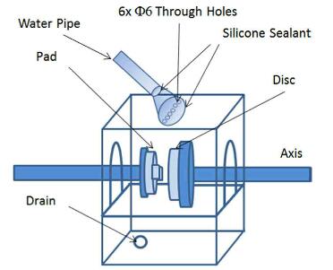
fig.2-schematically illustration of the water spray system attached to the braking test rig
braking contact interface. Before wet test started, the bedded brake was showered for 1 min to have friction surfaces soaked with enough water. During testing, a constant flowing rate, ~1 1/min, of water had been sprayed until the test programme was finished.
The braking test programme adapted in this study was started with an as-finished disc and pad on testing rig in ambient air environment, to have a brake fully bedded by completing bedding. A total of 200 braking stops were applied in a consecutive way. In order to examine friction surface in-between braking executions, a separate test programme was conducted; at an interested point the tested disc was taken off from the rig for necessary characterisation, before it was re-installed on the rig to carry on the prescribed test.
Surface characterisation: The micro-structure of a friction surface was examined by using optical microscopy on a MeF3 microscope under a polarised and differential interference contrast lighting condition, and scanning electron micro-scopy on Leo 1530vp FEG-SEM under an accelerating voltage of 10 kV. Energy Dispersive X-ray spectroscopy was used to examine the chemical composition.
Surface roughness, an arithmetic average of absolute values, was measured along the tangential direction of a braking contact track
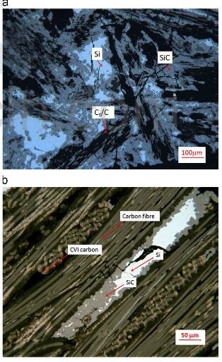
fig.3-optical microscopy images of as-polished surface of carbon ceramic composite disc in (a) Brake-H, and (b) Brake-L. the constituents are labelled in the image
with a surface profilometer by using a tip of 1 μm in radius. The moving speed of the tip was 0.5 mm/s and the scanning distance was 4 mm with a cut off, or sampling length, of 0.5mm.
Microstructure and chemicals on as-finished surface of brake disc and pad: Representative OM images of as-polished surface of the two
carbon ceramic composite discs studied in this paper are shown in Fig.3. C/C, SiC and Si regions are clearly differentiated under a polarised and DIC lighting condition, and are labelled in each image. The composite disc used in Brake-H has a significantly high SiC and Si content than that in Brake-L. Carbon fibers in Brake-H are short ones, and those in Brake-L were long ones. It is noted that both ceramic composites are highly heterogeneous in terms of the size of SiC/Si and C/C regions, and their distribution on the surface. For a ceramic composite manufactured via silicon-melt infiltration, Si in SiC/Si regions is always surrounded by SiC that is developed through the reaction between silicon melt and carbon; and carbon fibers in C/C regions are away wrapped by pyrolytic carbon that could be derived from carbonaceous resins, or gases, depending on which manufacture route is used. Microstructure for this type of composite is detailed in literature, and is out of interest of this paper.
However, the relative content of the constituents may relate to friction performance of a brake. By using image software, Image-J software, the area fractions of SiC, Si and C/C regions are estimated and summarized in Table 1. It is apparent that the fraction of SiC/Si regions on the brake disc surface of Brake-H is over 3 times of that of Brake-L. Therefore, it is interesting to know how the difference had influenced the brake’s friction performance.
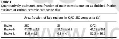
table.1-quantitatively extimated area fraction of main constituents on as-finished friction surface of carbon ceramic composite disc
Friction performance of a brake is tightly associated with the pad as well. A representative OM image of as-polished surface of a pad is
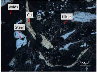
fig.4-optical microscopy images of as-polished surface of organic pad. the main constituents are labelled in the image
shown in Fig.4. The main constituents, such as steel and copper are distinguished easily and labelled in the image. Other constituents as fillers, abrasives, lubricants and binders cannot be recognised
clearly in an OM image. However, the typical chemical elements were detected with EDXS, and the results are summarised in Table.2. It should be noted that, due to the highly heterogeneous nature of a friction material, the quantitative value for each element is informative only, which can become the key sources of chemical footprints on a friction surface. As noted, a significant amount of Fe, Cu, C and O exist inside the pad.
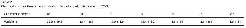
table.2-chemical composition of as-polished surface of a pad, detected with EDXS
related news /articles:
Friction performance of C/SiC brakes in different environment (3)
Friction performance of C/SiC brakes in different environment (5)
Friction performance of C/SiC brakes in different environment (7)
Friction performance of C/SiC brakes in different environment (8)