Friction performance in water spray environment: The averaged friction coefficient for each braking stop is presented in Fig.8 for the segment tested in water spray environment only. When water spray was applied, the friction coefficient dropped instantly to a level less
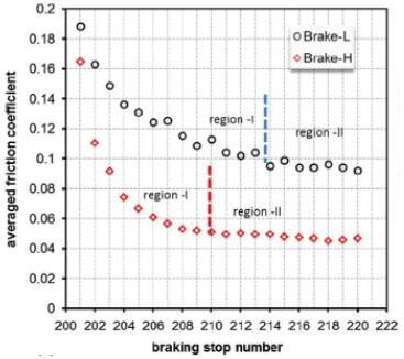
Fig.8-averaged friction coefficient of each braking stop for two C-SiC brake disc
than 0.2, more than 50% fall from a level at bedded stage. As the test continued with more braking stops added, the fall carried on, but in a decelerated trend.
The diagram shown in Fig.8 can be visually divided into two regimes. For Brake-H, region-I corresponds to the first 8 braking stops, indicating a clear fall trend of friction coefficient from 0.165 to 0.05, followed by a fairly stable friction at a level around 0.05, called region-Ⅱ. For Brake-L, the region-Ⅰ extended to a braking number of 14, showing a fall of friction coefficient from 0.19 to 0.095 before reaching to region-Ⅱ. Both regimes are labelled in fig.8.
Between the two brakes, there is little difference in variation pattern of friction coefficient with braking stop number, but friction coefficient for Brake-H was always 0.05-0.07 smaller than that for Brake-L. For both brakes, the stable friction coefficient under wet testing conditions, 0.05 for Brake-H and 0.095 for Brake-L, is well below an expected level for a brake that is suitable for road vehicles. Following the adhesion model shown in Eq.(3), one would expect that the friction contact area in Brake-H would be smaller than that in Brake-L, which will be examined and analysed below for the truth.
To eliminate any other factors that could cause such poor wet friction performance, we tested a cast iron brake disc against the same pad
carbon ceramic-racing car brake disc-CSiC-CFC-CC
under same testing conditions. The friction coefficients are plotted in Fig.9 from bedding to bedded stage in air, followed by water spray. The brakes was bedded quickly in ambient air. When water spray was applied, a stable friction was maintained in a same level as that after bedding. In fact, there was a fast increase of friction coefficient from 0.4-0.5 for braking stops after water spray was applied; a further increase to a level around 0.55-0.67 was observed as braking continued under such conditions. One may attribute (a) the high friction coefficient to the higher braking pressure used in this study, and (b) a reinforced ploughing friction mechanism that was demonstrated by clear ploughing grooves left on friction surface of cast iron. The earlier on might not have significant impact as the braking pressure is still inside the regime of braking pressure used by brakes of normal automotive vehicles. However, the later one could have more dominant impact as organic pad used for carbon ceramic brake disc is expected to be harder, which can plough the hardened surface of cast iron in a cold environment. Nonetheless, further understanding of cast iron brake’s friction is out of the range of this paper, and a quantitative study is needed.
The comparative study does suggest that neither testing conditions nor pad itself had any critical contribution to the poor wet friction performance of a ceramic composite brake. The problem ought to be ceramic composite disc itself, and non-boundary friction was hence reinforced due to the existence of water. Therefore, the following analysis will focus on the composite disc, including tomography and microstucture of its friction surface, as well as necessary conditions for non-boundary friction during braking.
related news /articles:
Friction performance of C/SiC brakes in different environment (5)
Applications of carbon fiber reinforced composite (3)-airplane brake discs
Friction performance of C/SiC brakes in different environment (6)
Friction performance of C/SiC brakes in different environment (2)