Friction surface after bedding and friction contact area: Representative OM and SEM images of the friction surfaces of the composite
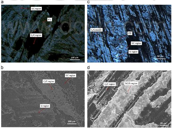
Fig.6-representative OM and SEM images of friction surface of a C-SiC composite brake disc.
discs, subjected to 200 braking stops in air, are shown in Fig.6. On both surfaces, transferred materials were clearly deposited in SiC+Si regions either as a continuous layer on top of the regions, as shown in Fig.6(a), or as fillers in crevices or craters that were likely formed through surface fracture during braking, as shown in Fig.6(b). It seems that the whole SiC/Si regions were in full friction contact during braking, based on this observation. In the C/C regions, transferred materials were deposited in a patched manner. Some became part of load bearing regions, along with carbon materials- particularly most of the exposed carbon fibers, but some were fairly powdery, which unlikely bore any load, or in contact with pad surface.
The observation shows that the change of SiC+Si content in the composites has little influence on the deposition of transferred materials on friction surfaces. The load bearing regions, or the contacted areas, included all SiC+Si regions, and part of the Cf/C regions. Most of these load-bearing contact regions on a fully bedded surface show white grey or dark grey contrast under OM imaging conditions. By using Image-J, the fraction of friction contact area on a brake disc is estimated as 76.8±8.3% and 5.2 ± 10.5% for Brake-H and Brake-L, respectively. The estimation gives a load bearing area ratio, fH/fL, of 1.34 for the disc in Brake-H to that in Brake-L, just slightly larger than the upper bound of ratio of friction coefficient, indicating the averaged friction coefficient of a braking stop is proportional to the fraction of friction contact regions, as predicted by Eq.(3).
On the other hand, it is necessary to examine the friction surface of the pads. Representative OM and SEM images of friction surface of
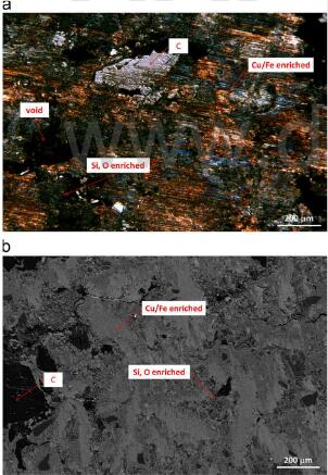
Fig.7-representative OM and SEM images of friction surface of an organic pad tested against a carbon ceramic composite disc
the organic pad, subjected to 200 braking stops by testing against the C/C-SiC composite disc in Brake-H, are presented in Fig.7. Three types of regions can be distinguished based on the contrast of the secondary electron image: white grey, dark grey and black, associated to copper and /or iron, silicon and oxygen, and carbon, respectively. The friction surface had been fully bedded, except ~20% voids remained, as estimated from OM images by using image-J. It is clear that the friction contact area on a pad surface was larger than that on a composite brake disc. Therefore, it should be a reasonable assumption that friction coefficient at bedded stage was dictated by the friction contact area on a composite disc.
As evidenced, all SiC/Si regions seem to be in friction contact during braking, it is therefore possible to estimate the fraction of friction contact area in Cf/C regions at bedded stage by following Eq.(3). With the measurements shown in Table 1 and the measured fraction, 76.8 ±8.3% and 57.2±10.5%, of all friction contact regions on a brake disc in Brake-H and Brake-L. respectively, we have estimated that 50.6% and 48.0% of C/C regions was in friction contact in Brake-H and Brake-L, respectively. The fairly close estimation implies that bedding had similar impact on all C/C regions in developing load bearing regions by either depositing transferred materials or abrasion. The fact that nearly half of surface of Cf/C regions might have contributed the friction contact during braking should be the main reason that SiC/Si content in a composite brake disc had a disproportionately impact on measurement of averaged friction coefficient of a braking stop.
It is not possible yet here to provide direct evidence why the Brake-H needed more braking stops for the bedding, owing to no systematic examination was done on the friction surfaces at bedding stage. The possible reasons can be speculated only: (a) different bedding speed of friction surface of a pad when it was tested against different brake disk; (b) different bedding speed in SiC/Si regions, probably owing to the significantly larger real contact pressure applied on SiC/Si regions in Brake-L, comparing to Brake-H, which could promote the bedding on both friction surfaces of brake disc and pad. Nonetheless, further experimental investigation is needed in order to have better understanding and sound conclusions.