C/SiC Brake disc and pad manufacture: All testing discs have a diameter of 60mm and thickness of 15mm, and were directly cored from the as-supplied material blocks by using core drill, followed by grinding to achieve the flatness and parallel requirements on friction surface. All testing surfaces were polished using a KEMET lapping machine. Polishing was carried out using three grades of diamond slurry: 68,8 and 3 μm, started from the coarse one and finished with the finest. The fine surface finish was adapted to minimise the difference of surface topography among the as-finished friction surface, which might influence the friction measurement. The drawing
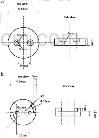
fig.1-Drawing of (a) brake disc, and (b) pad used for braking study on a laboratory-scale dynamometer.
of the disc is shown in fig.1(a).
The as-acquired pads were first cut into a ring shape with outer diameter of 50mm, inner diameter of 38mm and height of 4mm, followed by further machining to remove material off from the ring to achieve two symmetrically positioned arc segments; each segment corresponds to a quarter of the total length of the ring. The drawing of the pad is shown in FIg.1(b). The surface of the as machined pad was finished by 500 grade SiC sand paper before being used for test.
Braking test: The friction testing was conducted on a laboratory-scale dynamometer with inertia of 4.70 g/m2. Details on this testing rig are available in reference. The testing procedure used in this study is summarized here. For each braking stop execution, a disc was firstly accelerated to a rotation speed of around 10,000 rpm ±10% by compressed air, equivalent to a sliding speed of 20m/s at the circular position having an effective radius of the friction contact track. Such a sliding speed is close to the motor-way braking speed of a front brake designed for high end automotive vehicles. Then, a pad was pushed onto the disc with a constant brake pressure of 3.6 Mpa to decelerate the spinning of the disc until it was completely stopped. Note, braking pressure for a typical automotive vehicle is >1.2 Mpa, and could be close to 10Mpa in extreme situations, and the chosen pressure is inside this region. Same execution was repeated according to the requirements of each testing programme. For consecutive braking stop, the interval between executions was maintained the same as 5s.
For each braking stop, the rotation speed, braking load, and braking torque were collected by a data logger with a capture frequency of 50Hz. Friction coefficient was calculated using the following equation:
friction equation-1
Where T is braking torque, Po braking pressure, Se is the friction contact area (Se=1/8 ×π×(502-382)=414.48 mm2), and Re effective radius (22 mm here) of the friction contact track.
related news /articles:
Carbon fiber reinforced silicon carbide composites (C/SiC, C/C-SiC)-(1)
Friction performance of C/SiC brakes in different environment (4)
Friction performance of C/SiC brakes in different environment (8)
Friction performance of C/SiC brakes in different environment (5)