Friction plateaus in water spray environment: Images (a)-(f) in Fig.12 show the microstructure of the friction surface of a C/SiC composite disc in brake-H, intercepted after various numbers of braking execution in water spray. The transferred materials deposited at the bedded stage were largely wiped off, and SiC regions were subjected to continuous polishing.
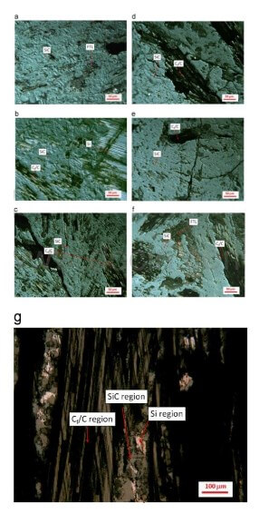
Fig.12-OM images of the friction surface on CC-SiC disc
Compared to the friction surface after bedding shown in Fig.12(a) after bedding, the SiC, Si and Cf/C regions after first braking stop were all exposed under OM imaging conditions, as labelled in Fig.12(b), showing most of the deposited friction transfer materials were not bonded strong enough on the surface. It is noted that some transferred materials were still left in Si regions, or inside voids on surface of Cf/C regions. The friction surface shows a rough morphology, largely defined by the tomography of the composite surface. As a key surface feature in SiC regions, the mechanical deformation kinks, developed during multiple braking in air, were still discernible.
After 3 braking stops, the change in Si and Cf/C regions was limited, but the mechanical deformation kinks became less discernible on the surface of SiC regions, as shown in Fig.12(c). After 8 braking stops, the surface of SiC became further smoothened without deformation kinks visible, apart from small voids, as shown in Fig.12(d). It is also noted that the exposed Si regions had transferred materials covered again up to this stage, showing dark-grey patches in SiC regions. As the braking continued, the polishing process just carried on, and SiC regions became even smoother, making voids on the surface become smaller and fewer, evidencing a significant polishing-off of the SiC surface without introducing any further surface cracking damage, as shown in Fig.12(e)-(f). There was little change in all Si regions, as they were covered by transfer materials, as well as in all Cf/C regions where no transferred firmly deposited, apart from powdery debris.
The brake disc of Brake-L experienced similar changes during braking under the same wet conditions. A representative image is shown in FIg.12(g) on the morphology of friction surface after 20 braking stops. SiC and Cf/C regions were clearly exposed; Si regions were covered by transferred materials.
The chemical composite on the friction surface was examined by EDXS, and representative spectrum acquired from SiC and Si is shown in Fig.13(a) and (b) respectively. In a SiC region, no other chemical elements were detected apart from Si and C, indicating no transferred materials on SIC surface. In a Si region. Cu/Zn and O detected along with Si, indicating a cupper/zinc containing friction layer was maintained on the surface of Si with strong bonding. The lack of other main chemicals from the pad, such as Fe, implies that copper and silicon might have been fused together in a favoured manner, as noted in previous research. The enriched O peak implies that, not only the friction transfer layer might have been oxidised, but also plenty of oxygen dissolved in Si region as well, which was evidenced in reference(16). In a Cf/C region, Si, O and C were the main chemical elements on the surface, indicating that the powdery debris were from the pad with chemical composition closer to silicates, which are used in pad as fillers.
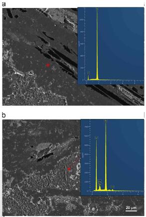
Fig.13-Representative EDXS spectrum acquired from a SiC and Si region respectively
The observation has demonstrated that SiC/Si regions were the main load bearing, or friction contact, regions on a composite brake disc surface. Whilst some carbon fibers might have contributed the friction contact area, the fraction was relatively small, and is not accounted in the following analysis, as a approximation. Hence, the real pressure applied on the contact regions should be largely determined by the fraction of SiC/Si regions on a friction surface. By using the real pressure, rather than the nominal pressure, the Stribeck curves can be re-plotted. Representative ones are shown in Fig.10(c). From this plot, we can infer that the higher coefficient for Brake-L in spray water environment is largely due to the higher contact pressure on friction plateaus during braking, comparing to those in Brake-H, as indicated by the nearly linear trend of the shaded straight bar.
As shown above, SiC/Si regions were the main friction contoact on surface of a ceramic composite disc to govern the friction performance. Therefore, the boundary friction conditions must be associated to the surface topography in these regions. During braking, two phenomena, removal of transferred materials and surface polish, observed on surface of these regions can reduce boundary friction and concurrently reinforce hydrodynamic friction. First, the remove of friction transfer materials could change either adhesion or confirmability between friction surfaces of pad and disc, or both, due to the chemicals on the friction surface become more inert and the increase of surface Young modulus. Secondly, the polish can directly reduce the height of asperities in these regions, making boundary contact less likely due to pressures on each asperity is reduced, and hydrodynamic friction becomes more sustainable even under relatively lower sliding speed. This is deemed to be the main reason for the observation that a gradual fall of friction coefficient for a braking stop when the braking stop number increased in water spray environment, as shown in regime-I in fig.8.
related news /articles:
Friction performance of C/SiC brakes in different environment (7)
Friction performance of C/SiC brakes in different environment (6)
Friction performance of C/SiC brakes in different environment (5)
Coatings for carbon-carbon composites (1)-SiC oxidation