The average wear and wear rate for each brake-stop run under different conditions are summarized in fig.10. Despite their longer setopping times, the AP specimens exhibited much lower weight losses than those of BI specimens due to the much lower friction coefficients. Specimens braked from the higher speed always suffered higher weight losses either due to their longer sliding times or their higher friction coefficients corresponding to more severe structural damage, as will discussed later.
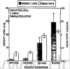
fig.10-average-wear-and-wear-rates-under-different-conditions
Typical surface morphology of AP specimens has been shown in fig.2(a). In this C-C composite, individual fibers as well as bundles were all bonded by the pyrolyzed matrix pitch, which had been pressure-infiltrated into the composite interior prior to ach carbonization treatment. Large and small pores and cracks exist throughout the composite.
After braking test from 1400 rev/min, the surface became smoother. While most of the small pores, which were observed on the AP surface, were filled with debris, the larger pores and individual fibers were recognizable. This type of surface with a thin, smooth debris film accompanied with a relatively low friction coefficient and low wear was classified as “typeⅠ” morphology in an earlier paper. As shown in Fig.11(c), the worn surface of AP/2000 exhibited a thicker debris film than that of AP/1400, but individual fibers were still recognizable. While the small pores were readily filled, the number of larger pores was greater than that on the AP/1400 surface. Apparently these pores were generated during the more severe sliding process of AP/2000.
The BI surface is featured by a thick powder debris layer, where most of the proes were filled with debris. The low magnification photograph of the entire disk showed a uniformly dark surface. As mentioned earlier, the BI surface was much rougher than the AP surface. As shown in an earlier report and the present friction coefficient data, this “bypeⅡ” worn surface was always accoompanied with a much higher friction coefficient and wear than those of type Ⅰ surface.
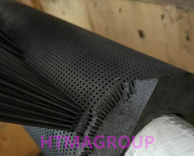
pitch coke carbon composite
After the braking test from 1400 rev/min, as shown in the photograph of Fig.12(a), patches of light regions were non-uniformly distributed in full or partial circles over the otherwise dark surface. SEM showed that the dark regions comprised the type Ⅱ powdery debris, while the smoother, light regions exhibited a “type Ⅱ” morphology.
According to an earlier study, this more lubricative type Ⅲ debris was evolved from the type Ⅱ powdery debris being rolled, compacted and pilled up layer by layer. The lubricating capability of the type Ⅲ debris can be seen from the declining friction coefficient at the early stage, when this debris started to develop. However, due to the weak mechanical bonding among layers, delamination easily occurred in the type Ⅲ debris regions. When the delamination occurred, thin fragments of debris broke off the surface and were transformed into type Ⅱ powdery debris again during the continued sliding process. While a portion of such powder escaped from the sliding surfaces contributing to the weight loss, other powder either fell into surface grooves/pores, or was subsequantly compacted to form typeⅢ debris again. The formation-disruption-re-formation behavior of the lubricative type Ⅲ debris may explain the undulating friction coefficient curve of BI/1400, as shwon in fig.7(a). Although the photograph showed that more light regions were generated, the surface of BI/2000 was severely damaged. SEM showed that little powdery debris was observed over the heavy delaminated light areas, while mroe powder appeared in the dark areas. Unlike the light regions generated on the BI/1400 surface, the non-uniformly distributed light regions on the BI/2000 surface were obviously incapable of lubricating during sliding. The severe structural damage is these regions could not be mended during subsequent sliding. This resulted in an unstable surface, which was responsible for the increasingly high friction coefficient and large weight loss during the second half of the braking process.
related news /articles:
Surface effect on braking behavior of PAN-pitch carbon fiber composite(5)
Friction performance of C/SiC brakes in different environment (6)
Friction performance of C/SiC brakes in different environment (8)
Friction performance of C/SiC brakes in different environment (10)