If a carbon composite is subjected to an ultrasonic source, low frequency waves penetrate to a greater depth than a higher frequency source
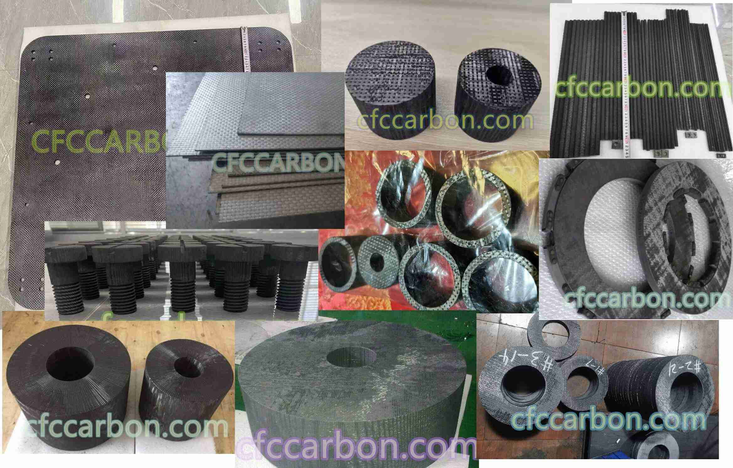
carbon fiber composite material manufacturer in China(1)
and are more sensitive to defects, but cannot be heard above 20 kHz. A compromise for frequency has to be selected between penetration and sensitivity. A stress wave has to be injected into the composite and the transmitted or reflected beam has to be monitored using piezoelectric transducers, which can send a pulse or receive the vibration as an electric signal. To obtain good results, the transducer must be effectively acoustically coupled. Air is a poor coupling medium, transmitting only 0.03% with a cfrp, whereas water transmits 72.3%. Greases and gels can also be used.
To obtain the most efficient coupling, it is necessary to immerse in a water hath, but this is not always practical and jet-probes have been developed where water is propelled in laminar flow. Alternatively, hand held probes can be used with a grease coupling medium.
To examine a laminate sheet, it is most convenient to measure the attenuation of the ultrasonic beam passing through it and there are three techniques which can be used:
- Use probes on either side of the laminate
- Use s single probe positioning a glass plate on the other side to reflect the beam
- More conveniently, use the back surface pulse echo
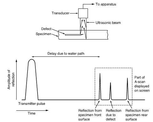
There are three ways to undertake these ultrasonic scans termed A-, B- and C- scans.
Figure 17.91 shows a typical A-scan using back surface echo, where the amplitude of the signal reflected from
scan representation of ultrasonic data
B-scan representation of ultrasonic data
C-scan representation of ultrasonic data
the top surface, back surface and defect are displayed on the y–axis of an oscilloscope with time on the x-axis.
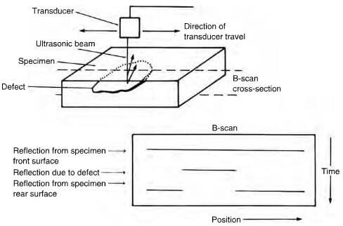
Figure 17.92 shows a B-scan which basically a series of A-scans taken in a straight line and recorded as a function of position on a storage oscilloscope, giving a picture of the cross-section along the line of scan.
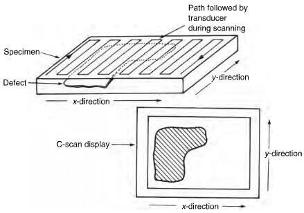
Figure 17.93 shows a C-scan, which is a representation of ultrasonic data where the scanning transducer has been moved to follow a rectilinear raster and the transducer position and amplitude of the signal are recorded on an X-Y plotter. Figure 17.94 depicts the damage incurred in the form of de-lamination by a cfrp laminate when impacted.
Low energy radiation can penetrate reasonable thicknesses of a polymer matrix composite and 1 MeV X-rays are able to penetrate 500 mm of polymer. The cfrp have low X-ray absorption and consequently, low voltage,
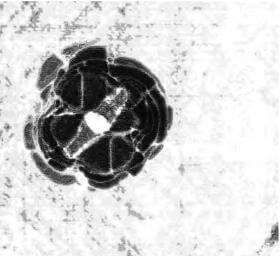
Ultrasonic S-scan of cfrp laminate showing an area of impact induced delamination
low energy X-ray have to be used in conjunction with high contrast recording techniques, which can then detect transverse cracks and inclusions. Unfortunately, carbon fibers and resin matrices have similar mass absorption coefficients and cannot be differentiated. Glass, on the other hand, can be readily detected and can be used in composite construction as a radio-opaque tracer, showing the direction of fiber lay-up.
Acoustic emission can be used for testing pressure vessels and is not strictly a non-destructive test as it involves listening to the propagation of damage when subjected to an applied stress.
related news /articles:
Friction performance of C/SiC brakes in different environment (3)
Friction performance of C/SiC brakes in different environment (1)
Application of Carbon fibers on new structures with cfrp
Core materials for carbon fiber composites