Testing of carbon fiber composite-Introduction
In the composite tests to follow, the reader is referred to text books on classical beam theory should one wish to derive the theory. Many excellent publications have been written on the subject of composite materials covering analysis, mechanics, principles and performance.
Figure 17.30 shows the principal coordinate axes for unidirectional lamina.
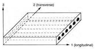
principal coordinate axes for unidirectional lamina
Figure 17.31 shows associated deformations of composite materials.
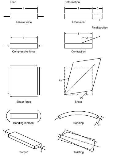
the loads with associated deformations of composite materials.
Preparation of composite specimen from wet resins
A matched metal mold must be carefully ground from hardened steel and the finished dimensions carefully checked. The mold, when new, should be coated wit silicone grease and baked for 24 h at 200C, to acquire a patina with an improved release. All assembly set screws and their sockets should be smeared with silicone grease to prevent resin penetration and ensure their effective removal after resin cure. Prior to lay-up, the mold should be evenly coated with a mold release spray, positioned on a hotplate and the bottom of the mold coated with a thin layer of resin applied with a small paintbrush. Tows should be coated with resin heated to 50-60C to lower the viscosity and achieve thorough penetration and carefully placed in the mold under tension to accomplish the best practical degree of alignment. The most common problems experienced when molding specimens are – failure to have used thoroughly clean molds and set screws that were insufficiently tightened. All molds should be thoroughly inspected for cleanliness before use and it will be found advantageous to use an air operated torque wrench to ensure that the correct and even degree of tightness is used for the set screws. In the early days, when there was little fiber available for test, the length of tow cut for insertion into the mold tended to be too short and once resin had penetrated the free ends of the tow, and the mold was closed, the resin simply extruded outwards together with the fiber. It is therefore important to ensure that the free ends of tow do not become impregnated with resin and there is sufficient dry fiber to achieve some interfilament cohesion to prevent possible extrusion from the mold as it is closed. If G-clamps are used to clamp the mold together during the cure cycle, it is advisable to use the forged version for greater strength and reliability.
Figure 17.32 shows typical packing fraction distributions for circular section fibers and Figure 17.33 shows the spacing between 7 um diameter filaments for different packing fractions, generally a Vf of 60-65% is used and an accepted practice is to normalize the resin content of the composite to 60% by applying the Law of Mixtures.
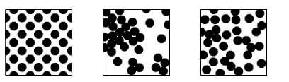
packing fraction distributions for round fibers
The number of tows required when making 1 60% Vf composite bar would be:
Number of tows=0.60wtp/ML
Where w=width of specimen
t=thickness of specimen
p=density of carbon fiber
ML=mass per unit length of carbon fiber tow