The fabrication of CC composites using pitch matrix materials involves first infiltrating the fiber preform with pitch before heating to carbonization temperature. As discussed previously, during carbonization various gases are evolved, and providing the rate of heating is slow, the isotropic pitch is transformed gradually to mesophase.
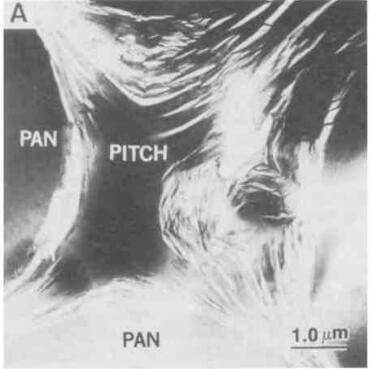
The molecular structure of mesophase has been described to consist of discotic liquid crystals aligned parallel to one another. Although these layers exhibit high in-plane strength and stiffness, they can easily shear relative to each other. Because of this, such layers will tend to preferentially orient themselves parallel to any surface across which they move. Regardless of the absolute mechanism of orientation, the result is that in a carbon matrix derived from pitch, each fiber will be surrounded by a matrix of highly aligned, strong-stiff graphitic basal planes
Figure 10 is an optical micrograph of a 3D CC composite composed of PAN fibers and a coal tar pitch matrix. The
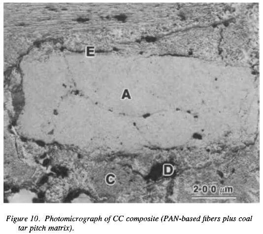
photomicrograph of CC composite (PAN-based fibers plus coal tar pitch matrix)
composite was processed using a multiple high pressure impregnation carbonization technique at 206Mpa pressure to densify the composite. Figure 10 position A shows a transversely oriented fiber bundle surrounded by the interbundle matrix (position C). The composite contains a significant amount of porosity (positions D and E) of which there are two types. The larger voids (position D) were formed as a result of volatilization during carbonization/graphitization cycles, whereas the cracks/fissures (position E) were formed due to shrinkage of the matrix carbon during the cool down from the processing temperature. A large proportion of the voids are infilled with a resinous carbon added to complete the densification process.
The development of the mesophase within the interbundle matrix of the composite is not always uniform. The structure of some of the matrix regions is coarse-grained mosaic whereas the structure of other regions is fine-grained mosaic. This variation in the optical textures of the binder-coke causes differences in mechanical properties and chemical reactivity of the composite.
Variations in processing conditions have reportedly affected the matrix orientation. The alignment of the graphitic
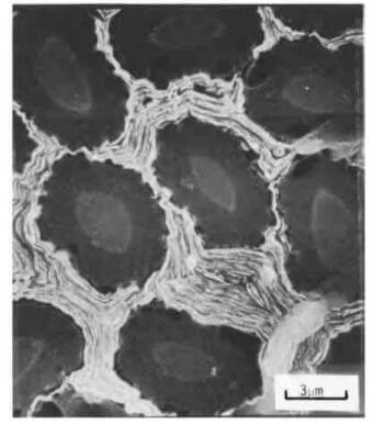
SEM micrograph of transverse section of fiber bundle showing fiberlintrabundle matrix after etching with atomic oxygen at 100C for 3hr.
planes under low-temperature carbonization is primarily controlled by the flow motion of mesophase. High pressures have been reported to favor a transversely aligned matrix. Other factors also seem to be important because that both parallel and transversely oriented graphite planes were produced in a specimen carbonized under atmospheric pressure. Although local variations in crystallographic orientation are observed, pitch matrix composites generally exhibit microstructures in which the fibers are surrounded by coaxial, graphitic sheaths.
The example shown in figure 12 is an SEM micrograph of a PAN-pitch composite etched in this way. This micrograph clearly shows that the intrabundle matrix platelets are parallel to the fiber surface. As can be seen from this transverse section, the fiber bundles appear fully densified, although the interface between the fiber and matrix appears to be quite reactive since it has been etched preferentially. The presence of a central core in the PAN fiber shown in this figure has been discussed in the literature and is attributed to graphitization of partially stabilized PAN fibers.
CC composite
CC composite
In summary, the microstructural investigation of pitch matrix composites indicates:
- The carbon produced from pitch precursor materials is highly graphitic and generally exhibits a flow-type morphology.
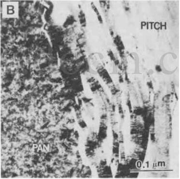
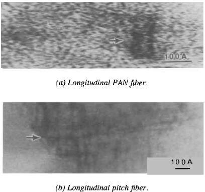
- Although the bonding between the PAN fibers and the mesophase pitch matrix appears continuous at low magnifications, high-magnification TEM studies reveal numerous microcracks along the fiber-matrix interface, each separated by what appear to be well-bonded regions.
- The microcracks within the matrix are smaller and denser when they are near the interface.
- The crystallite size in mesophasic matrics is large compared to that in PAN fibers.
- The crystallites in the matrix are aligned parallel to the fiber surface in a range approximately 0.2um to 0.6um from the fiber surface; thereafter, they tend to become more random.
CC composite