It follows from experimental data that a marked factor with a capacity in the HTT stage to reduce user properties for carbon-carbon billets may be realization of internal production and residual stresses in the form of geometric distortion of an object. In order to analyze the moving forces additional research was carried for the change in specimen shape of plates of carbonized material with a size of 1050×55×4mm during HTT. Carbon threads in a plate were placed with deviation from the longitudinal axis of ±15%. Specimens for measurement were cut in four directions: along the plate axis; along a reinforcing thread; across a plate; and across the direction of a thread. A change in specimen dimensions during heating, simulating high-temperature processing, was carried
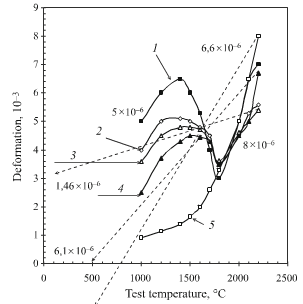
fig.4-results of dilatometric study of specimen material deformation for plates 4 mm thick
dilatometrically with heating a specimen and then cooling to room temperature. Plate material was prepared by standard technology based on industrial carbon threads, heat treated to 2200-2400°C. Results of measurements are presented in fig.4. First it is noted that the change in current dimensions during primary heating does not entirely coincide the current dimensions of a specimen during cooling. The track of a curve for specimen dimensions measurement during cooling, as established, then entirely coincides with its physical thermal expansion during subsequent determination of LTEC by the standard procedure. It is apparent that as a result of primary heating there is completion of structure rebuilding, and therefore subsequently we have work with a stable material over the whole treatment temperature range.
A complex picture for the change in shape and dimensions of plate material during primary heating is reflected by the appearance of action of a number of factors. Up to 1400°C material expansion occurs with intensity, markedly less than should follow from the physical ensuing LETC, which means appearance of restricted shape changes. Restriction of deformation in the plane of a plate apparently is compressive in nature. The resultant expansion during heating differs by a factor of two in relation to the local reinforcement scheme, and anisotropy. The perimeter of a plate is retained as a whole, and there are no separations or delamination of plate edges. This means unavoidable formation of a complex three dimensional thermally stressed state, even in a freely supported rectangular plate. This condition develops, as shown in figs.1 and 2, in the form of distortion over the height of a shell and plate. Above 1400°C the picture of deformation of a plate changes sharply. In the plane of a plate there is shrinkage. At the same time through the thickness of a plate expansion continues and even relatively accelerates. This may mean that compression within the plane of a plate continues under conditions of temporary and sharp falls in load resistance if a carbon composite substance. Expansion through the thickness means that tensile stresses predominate. The capacity to resist a mechanical load was restored from ~1800°C. With a higher temperature expansion proceeds with a marked advance compared with that following for ensuing LETC. In this temperature range treatment corresponds with the results of shape change of objects presented in Fig.3. As a reulst of this a plate during heating and after cooling has new dimensions, not coinciding with those that existed after carbonization immediately before HTT. The dimensions of specimens corresponding to the treatment temperature limit and after cooling to room temperature are connected in fig.4 by a broken line. Differences between them, related to difference in temperature, give an average value of LTEC. For plates with a size up to 1000×1000 mm absolute changes in shape in the plane of a layer may be along a plate (1.46×10⁻⁶°C-1)×2200°C ×1000 mm=3.2mm, and across it 14.5 mm. Deformation without plate failure is levelled out by stresses within the limits of an object. Here different parts are deformed differently in absolute value and direction. Shinkage in a plane may lead to loss of stability, warping, “twisting” of an object in the weakest direction. These directions for materials based on high-modulus carbon threads may be across a plate, and in the case of material based on low-modulus carbon cloths of viscose at an angle of 45°, and also a direction over the weft, where elasticity modulus is half that in the direction of the warp.