Residual stress, a well-known phenomennon in composites, is frequently caused by thermal expansion mismatch between reinforcement and matrix phases. Particularly for carbon-carbon composites, the consequences of thermal expansion can be severe. The extreme thermal expansion anisotropy of the graphite crystal perpendicular and parallel to the basal plane and the high stiffness parallel to the basal plane, can precipitate fracture in large composite structures during processing.
Given the high temperatures involved in processing, direct evidence for residual stress is difficult to obtain in such composites. Some work has been done by measuring cracking in processed cylindrical carbon-carbon composites. Curvature or warping of machined bars of nonhomogeneous material is often observed when local variations of material properties create residual stress. This report discusses evidence for residual stress obtained by cutting thin slices from a 3D cartesian weave carbon-carbon composite and measuring the residual curvature.
In preparing slices of various thicknesses, we observed that some slices of less than a certain thickness would not remain straight but would warp noticeably (fig.1). Further investigation discovered the warping to be related to both the thickness of the slice relative to the yarn spacing and the slice’s location in the bulk composite.
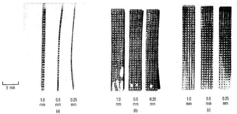
fig.1-X-direction-slices-of-2-2-3-composite
The material analyzed a x-, y-, and z-directions cartesian weave composites, using PAN-based carbon yarn of approximately 380Gpa modulus. The x and y site specing were 0.76mm, and the z site spacing were 0.84mm. The composite was fabricated from a 3D, carbon yarn preform by repeated densification by chemical vapor deposition and graphitization to temperature above 2500°C. The matrix material was graphite, and the composite had an overall mathanol immersion density of 1.9*10-3 g/cm3.
Slices 27mm long, 4mm wide, and 0.25, 0.5, and 1mm thick were cut from the bulk composite. The length was parallel to the x-direction, and the width was parallel to the y-direction. Some of the 0.25-mm-thick slices curved markedly (Fig.1a); for thicker slices, the curvature was less severe. From the optical micrographs (Figs. 1b and c) of the front and back surface of the slices, which display the directions of fiber reinforcement in the material, one can conclude that the curvature is caused by asymmetric fiber reinforcement of opposite faces of the thin slice coupled with residual thermal stress.
Figure 2 diagrams the geometry of a unit cell. The site spacing along the thickness direction of the slice corresponds to 0.76mm. Thus, a slice cut thinner than that will contain only part o a unit cell through the thickness. Because the location of the slice was selected at random, the amount of x-direction reinforcing carbon fiber versus matrix material and y- and z-direction reinforcing fiber was somewhat variable in the slice.
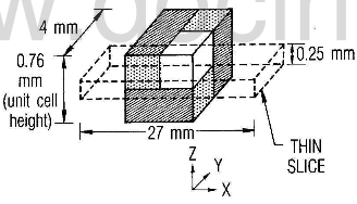
Fig.2-geometry of unit cell and thin slice along x-direction from 2-2-3 composite
In Figs.1b and c, x-direction reinforcing filaments in the 0.25-mm-thick slice are evident along almost the entire back surface, but none is showing on the front, although y-direction reinforcing fiber are. Matrix pockets and ends of z-direction filaments appear on both front and back faces. Because of the thermal expansion anisotropy of the fiber, the matrix and transverse directions of the y- and z-yarns in this sample tend to shrink more in cooling from elevated temperature than the longitudinal direction of the x-yarns; so the x-direction yarns are in residual compression while the matix and transverse fibers are in residual tension. The four components–matrix and yarns in three directions–will require good bonding under conditions of local thermal expansion mismatc to retain the residual stresses.
The x-y surface of the sample is not perfectly parallel to the x-direction yarns, so the thickness of these yarns varies along the length of the sample, as the nonuniformity of the curvature along the sample illustrateds. Given both this nonuniformity, which implies variation with position of the effective bending stiffness, EI, and the asymmetry of the sample with respect to the neutral surface, the relation of the composite curvature to the individual constituent properties is not simple to analyze. However, comparison in terms of a similar beam of homogeneous, isotropic material is instructive.