In the early days of the carbon fiber electric lamp filament, it was practice to coat carbonized rayon filaments with pyrolytic graphite to improve the mechanical properties of the lamp filament.
Using the chemical vapor deposition (CVD) process, a gas such as methane can be cracked onto, say a carbon substrate and when the temperature is about 1100C, it forms pyrolytic carbon, which has an itotropic nature. At 1000-1700C, pyrolytic graphite is formed. The coating can be deposited on the substrate and, if sufficiently thick, can be removed as a free-standing object (cf CVD diamond).
In the 1950s, W. Watt of carbon fiber fame at the Royal Aircraft Establishment, with A.R.G.Brown, carried out work in coating graphite rods with pyrolytic graphite using methane gas at 2100C. They obtained a coating with a density of 2.17g/cm3, which was confirmed by X-ray analysis to have a highly preferred orientation. The density of the material produced at 1700C, however, was 1.12 g/cm3 and only increased to 1.52 g/cm3 when heated at 2800C, probably due to the initial deposition of soot-like particles, which acted as nuclei for the depositing graphite. Later, with W. Johnson, also of carbon fiber fame, the trio developed this work to study the thermal conductivity of the pyrolytic graphite deposited at 2100C and further heat treated to 2600C to obtain uniformity and they found an interesting anisotropy, obtaining for the longitudinal plane, a value some three hundred times greater than the value for the radial. This work on pyrolytic graphite was to form a valuable background for Watt and Johnson’s subsequent work at RAE on PAN-based carbon fibers.
The structure and properties of pyrolytic deposits are influenced by a number of factors, of which temperature is the most important. The size of the crystallites and their degree of preferred orientation increases with temperature, whilst the interlayer spacing decreases. Typical values for the density, crystallite diameter and crystallite height for pyrolytic carbon formed from cyclopentadiene at 930C and graphitized at 2700C. The density of 2.261 g/cm3 closely approaches the value for ideal graphite (2.269g/cm3)
Pyrolytic graphite can be prepared through a CVD process by thermally decomposing a hydrocarbon gas such as methane, ethylene or acetylene at about 1100C by the induction heating of a substrate undertaken at either a low pressure, when the product tends to be isotropic or, at pressures upto 1 atm, when it is necessary to dilute with a non-reactive gas such as argon or hydrogen to control the depositon process.
In a simple from, the reaction can be shown as
CH4→ C+2H2
However, it is really more complex and proceeds via the formation of benzene, various polyaromatic hydrocarbons and is finally deposited as carbon. Other CVD deposition techniques use a fluidized bed and plasma. A variation of the CVD process used for the production of carbon-carbon employs a chemical vapor infiltration (CVI) technique, where the reactive medium diffuses into a porous substrate, such as a 3D fiber construction, but any by-products formed must be allowed to diffuse outwards, rendering the process extremely slow.
Basically, pyrolytic graphite has a turbostratric structure, which is an aggregate of graphite crystallites that can
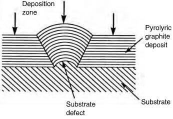
effect of substrate defect on deposited structure of pyrolytic graphite
exist in certain conditions as an almost parallel array, forming a near perfect graphite crystal. By careful control, the structure of the deposit can be columnar, laminar or isotropic. The cleanliness and geometry of the substrate plays an important role in the mode of deposition and Figure 2.29 shows the effect of a surface defect on the structure of the deposit. A columnar structure has the crystallites aligned with the basal planes parallel to the substrate and as deposition proceeds, the columnar structures widen, becoming cone-shaped with increasing grain size, which is not a desirable factor. This cone formation can be controlled by permitting soot particles to form on the surface, providing new growth sites (figure 2.30). A laminar structure comprises a number of parallel layers, which can be concentric if deposited on either a fiber, or a particle. Columnar and laminar structures are optically active
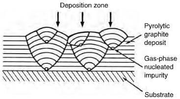
effect of gas phase nucleated impurities on deposited structure of pyrolytc graphite.
to polarized light and can be readily graphitized at 2500C under pressure, will produce highly oriented pyrolytic graphite (HOPG), which is an almost ideal graphite crystal.