The simulated domain is composed by a composite region topped by a fluid region. The composite region itself contains fluid voxels representing the pores and two types of solid voxels representing the different carbon phases.
In problem (Eqs. (2)-(4)), the coupling between transfer equations and surface recession is not explicit. The mass transfer problem depends on the surface evolution through the geometry of ∑. Moreover, the displacement of the local frame in the global frame requires the knowledge of the average recession velocity. In order to produce a weak description of these coupling, the following loop is built:
1. Solve the concentration field in the local frame.
2. Evaluate the local recession velocities in the global frame.
3. Perform solid displacement in the local frame.
In order to have a complete form of the model, boundary conditions must be added to the previous balances. A dirichlet condition c=co is chosen at the upper boundary and c=0 at the bottom boundry. As the reactant does not diffuse in the solid phase, this condition has no impact on the simulations of dense composites. When the simulated composite is porous, the solid domin is chosen thick enough to produce a total consumption of the reactant before the bottom of the domain. Periodicity conditions are used along the vertical sides. The initial surface of the composite is chosen perfectly flat and the initial concentration field is zero: c(x, t=0)=0. Because the recession time is large compared to diffusion time, the concentration field reaches a steady-state long before any significant first change is noticed in the wall position.
The diffusion-reaction problem is solved implicitly. Once the concentration field is obtained, the local recession velocities in the global frame are evaluated from Eq.(4). The evolved surface is then given by the use of PLIC formulation. The obtained algorithm is implemented into a FORTRAN 90 code later referred to as DiAbl3D.
The program has been tested on an ideal computational cell described in (6). An analytical expression has been derived for the roughness morphology; it extends the results given in (24) to the case of diffusion/reaction competition. The numerial results match satisfactorily the predicted surface equations, as well as the numerical results obtained by another code. Fig.4 shows a rather good agreement between a simulated fiber profile and the analytical shape for intermediate values of Da. When Da becomes very close to zero, the code is in perfect agreement with the predicted shape, which is a straight cone.
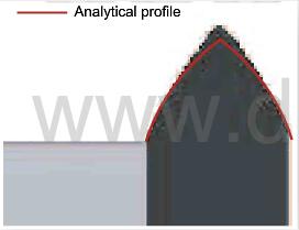
fig.4-steady-ablation-profile-of-a-cylindrical-fiber-emerging-from-a-matrix
Roughness evolution of actual C/C composites:
In this section, the surface evolution of two different classes of composites, i.e., with two different kinds of reinforcement architectures, is studied.
4D reinforced structures:
The 4D composite is reinforced by millimetric bundles of parallel fibers organized following the four inner diagonals of a cube, as explained in (42.43) and illustrated by the elementary pattern represented in Fig.6, where the cylindrical reinforcements are shown in dark, and the inter-bundle matrix is shown in light. Their typical diameter size is milimetric. The bundles are themselves constituted by a dense packing of parallel fibers embedded in a carbon matrix.
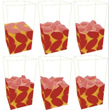
fig.6-Evolution of the composite at millimeter scale for the 4D structure