Infiltrating a carbon fiber preform with a reactive gas leads to the deposition of a carbon matrix and directly produces a CC composite. No subsequent thermal degradation step is necessary. However, pyrolytic carbon tends to deposit preferentially on the surface of the composite being fabricated, thereby blocking surface porosity. Infiltration can only be continued after terminating the densification process and removing the surface crust. Most isothermal depositions are carried out at a temperature low enough to limit the rate of surface deposition, yet high enough to assure an economically viable commercial process. The temperature of reaction has been shown to sensitively affect the density and the microstructure of the deposit, which in turn will affect the resulting properties of the CC composite product.
A typical photomicrograph of CVI carbon infiltrated into a PAN fiber preform is shown in figure 27. this micrograph
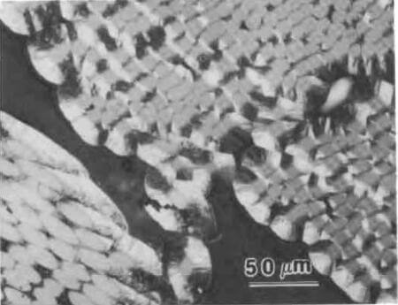
optical photomicrograph of interior region of PAN-CVI CC composite
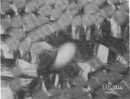
optical photomicrograph of closed porosity in PAN-CVI CC composite
shows the presence of large voids in some parts of the specimen. The CVI deposit consists of two structures: an isotropic phase immediately adjacent to the fiber surface and a second highly oriented lamellar structure. The extinction contours generated indicate that the basal planes of this second structure are circumferentially oriented approximately parallel to the fiber surface. The thickness of the deposit varies with fiber spacing and is thickest within the large open pores.
3D 4D carbon fiber composite material manufacturer factory -airplane brake disc plates sheets U L profiles-2D(6)
A higher magnification micrograph of the same composite is shown in figure 28, which shows more clearly the structure of the CVI deposits. In this particular region, the CVI deposit appears to have pinched off the pore so that subsequent infiltration would not be expected to be effective. The bonding between the isotropic CVI layer and the fiber, and between the two CVI layers looks continuous, with no evidence of fissures or cracking. cfccarbon.com
The continuous nature of the interface between the fiber and the isotropic matrix is confirmed by the TEM dark-field micrograph. See figure 29. The SAD studies suggest that the isotropic layer is composed of small randomly oriented crystallites, while the laminar structure consists of larger highly oriented crystallites. It is interesting that the interface between PAN fibers and isotropic CVI and between pitch fibers and isotropic CVI is continuous. Thus, the development of such an interface appears to depend more on CVI structure than on individual fiber type. The laminar CVI carbon contains many narrow slit-shaped microfissures that are generally <1um in length and <0.1um in width. This type of cracking is similar to that observed in pitch matrices and indicates that the strength of the bonds between individual crystallite platelets within the lamellar matrix is weaker, in some places, than the bond between the isotropic CVI and the PAN fiber.
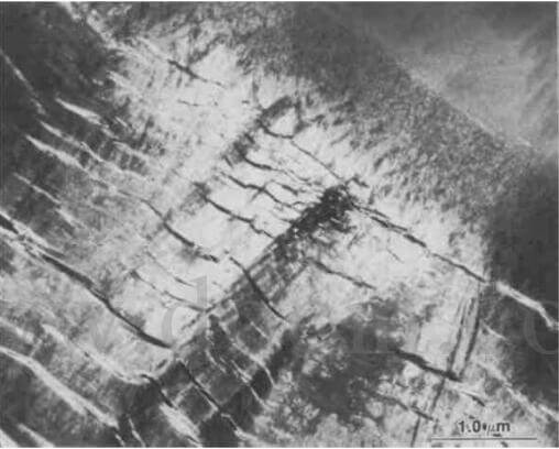
TEM dark-field image of CVI deposit on PAN fiber showing gradual transition from grainy isotropic to laminar structure
TEM dark-field image of CVI deposit on PAN fiber showing gradual transition from grainy isotropic to laminar structure
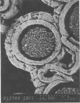
A photomicrograph of pitch fibers infiltrated with CVI carbon is shown in figure 30. In this case, conditions of deposition were such that no detectable isotropic layer was observed adjacent to the fiber surface. The CVI carbon exhibits optically anisotropic characteristics and has a rough lamellar structure. At this low magnification, it is difficult to observe if the interface between the fiber and matrix is microcracked, or if microcracks are present within the CVI deposit. Figure 31 shows an SEM micrograph of the same composite after etching with atomic oxygen. The interface between the fiber and CVI matrix is cracked. It should be noted that while the fiber matrix interface is this specimen is cracked, the corresponding interface shown in figure 29 is not. Since both composites were exposed to similar heat treatments, it can be concluded that the bonding between isotropic CVI and fiber is stronger than the bonding between lamellar CVI and fiber.
In summary, the microstructural investigation of CVI matrix composites indicates:
- Pyrolytic carbon tends to deposit preferentially on the surface of the composite being fabricated, thereby blocking surface porosity.
- The structure of carbon produced from CVI deposits can vary from isotropic to highly oriented anisotropic, depending on processing conditions.
- Bonding between isotropic CVI matrices and fibers is stronger than the bonding between lamellar CVI matrices and fibers.
- The lamellar CVI deposits contain many narrow, slit-shaped microfissures that are generally <1um in length and <0.1um in width. The isotropic CVI deposits contained no cracks.
Contact Us
related news /articles:
Carbon fiber carbon matrix composites manufacturing processes
CVI CVD Carbon Carbon Composite Material, Manufacturer in China
The various structures of pyrolytic graphite-(1)