Key words: C/C composite material; ZrC; mechanical property; anti-ablation material
The solid rocket motor (SRM) has a simple structure, has a series of advantages such as maneuverability, reliability, and easy maintenance, and is mainly used as a power device for various missiles and launch vehicles [1]. The SRM is uncooled, and the throat lining suffers from the most severe ablation environment during the working process. The throat lining material not only bears the thermal load and mechanical impact of high temperature, high pressure, and high velocity gas, but also withstands
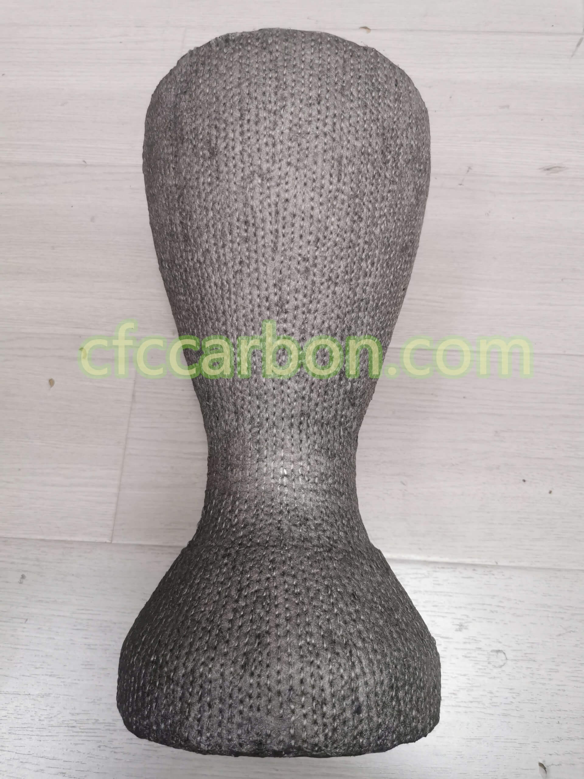
Ablation material-carbon fiber composite-CC-CFC-HC-PG-KSD (4)
chemical corrosion[1, 2]. Carbon/carbon (C/C) composites have a series of excellent properties such as low density, low thermal expansion coefficient, high specific strength/modulus, and anti-ablation [3]. Since the 1970s, the application of this material in SRM throat lining has greatly improved the impulse-to-mass ratio and reliability of SRM, and it is considered to be the most ideal throat lining material[4, 5]. With the application of high-energy propellants and the strict requirements of SRM on nozzle light weight, high efficiency, high impact-to-mass ratio, and high reliability, higher requirements are placed on the ablation resistance of throat lining materials.
Introducing ultra-high temperature ceramics (UHTCs) into C/C composites has become a key technology to improve the ablation resistance of the material [5]. For this reason, researchers have invented a variety of methods to introduce UHTCs into C/C composites, mainly including: hot pressing method[6, 7], powder slurry infiltration method[8], reactive melt infiltration method (RMI) [9, 10, 11], polymer impregnation pyrolysis (PIP) [12, 13, 14] and refractory metal inorganic salt solution impregnation [15, 16, 17, 18], etc. The hot pressing method cannot prepare products with complex shapes and causes great damage to fibers; the uniformity of UHTCs particles introduced by the powder slurry impregnation method is difficult to control; compared with the molten metal liquid of the RMI method and the high-temperature pyrolysis precursor of the PIP method, The refractory metal inorganic salt solution impregnation method adopts the water/alcohol solution of inorganic salt, and the impregnation process is carried out at room temperature, without multiple cycles, and the cost is greatly reduced. At the same time, no toxic gas is generated during the impregnation process, and the process is easy to control. The C/C-ZrC[15] and C/C-HfC[16] composites prepared by this method have excellent ablation resistance, and the only research results on the mechanical properties of C/C-HfC composites[17 , 18] showed that the mechanical properties of the material decreased with the increase of HfC content, but the reasons for the decrease in material properties were not further studied. So far, there is no report on the mechanical properties of C/C-ZrC composites prepared by this method.
In this study, C/C-ZrC composites with different ZrC content were prepared by ZrOCl2 solution impregnation method combined with thermal gradient chemical vapor infiltration (TCVI) and high temperature graphitization process, and the influence of ZrC on the mechanical properties of C/C composites was studied. By characterizing and analyzing the microstructure and bending properties of the material, the effects of ZrC on the properties of the fiber-matrix interface and the properties of the carbon matrix were studied, and the mechanism of ZrC was revealed.
1 Experimental method
1.1 Raw materials
The carbon fiber prefabricated body is a needle-punched integral carbon felt, which is formed by intersecting and puncturing carbon fiber non-woven fabrics and mesh tires, with an apparent density of ~0.20 g/cm3 and a volume fraction of carbon fibers of ~10%; methane (from urban pipelines natural gas); zirconium oxychloride (ZrOCl2 8H2O, ); high-purity nitrogen (purity ≥ 99.999vol%); high-purity argon (purity ≥ 99.999vol%).
1.2 Material preparation
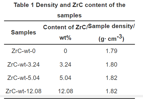
Table 1-density and ZrC content of the sample
First, impregnate a certain mass of carbon felt in a zirconium oxychloride aqueous solution of a specific concentration, keep it in the impregnation solution for 8–10 h, take it out, and dry it in an oven at 100–150°C. The felt was heat-treated at 500-600°C for 1 h in a nitrogen atmosphere to transform ZrOCl2·8H2O into ZrO2. After weighing the carbon felt containing ZrO2, TCVI densification was carried out with methane as the carbon source, and finally graphitization was carried out at 2500 °C under the protection of high-purity argon, and weighed after cooling in the furnace to calculate the ZrC in C/C composites. content in. The final densities and ZrC contents of the prepared composites are listed in Table 1.
1.3 Mechanical property test
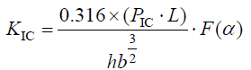
The C/C-ZrC composite blank was machined into a 55 mm × 10 mm × 4 mm cuboid specimen along the direction of carbon fiber layup (parallel to the fiber direction, XY plane), and the bending performance test was carried out (obtaining the bending strength and elastic modulus Amount), the fracture toughness test sample is to open a 0.2 mm wide and 2 mm deep cut on the cuboid sample. Using the three-point bending method, the bending mechanical properties of the materials were tested on a computer-controlled electronic universal testing machine (equipment model CMT5304-30KN, Shenzhen Xinsansi Material Testing Co., Ltd.), and 10 samples of each composite material were used. Test conditions: the span is 40 mm, the span-to-span ratio is 10, the loading speed is 0.2 mm/min, and the load-displacement curve is recorded simultaneously. Fracture toughness (KIC) is calculated according to formulas (1) and (2).
(1)
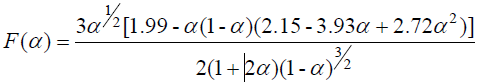
The specific form of F(α) is:
(2)
In the formula, PIC-the maximum load at fracture, N; L-span, mm; b-the width of the sample, mm; h-the thickness of the sample, mm; .
1.4 Material Characterization
The phase composition of the material was analyzed by χ’Pert Pro MPD X-ray diffraction (XRD), and the microscopic morphology of the material was observed by JSM-6460 and SUPR A55 field emission scanning electron microscope (SEM). Energy X-ray spectroscopy (EDX) was used to analyze the elements of the material, and JEOL-2100F field emission transmission electron microscope (TEM) was used to observe and analyze the microstructure of the material.
2 Results and discussion
2.1 Material microstructure and morphology
Before and after TCVI densification, zirconium compounds exist in the form of monoclinic ZrO2 and a small amount of
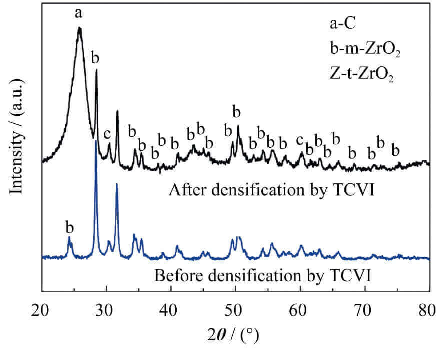
Fig. 1 XRD patterns of zirconium-containing carbon felt before and after densification by TCVI process
tetragonal ZrO2 (Fig. 1), indicating that pyrolytic carbon did not react with ZrO2 during TCVI densification. Combined with the SEM pictures, it can be seen that the overall distribution of ZrO2 in the carbon felt is relatively uniform (Figure 2(a)), but the content of ZrO2 will be higher in places where the fibers are dense (Figure 2(b)), and the carbon felt containing ZrO2 is densified After (C/C-ZrO2 composite) still maintains this distribution characteristics (Figure 2 (c)). These characteristics are closely related to the introduction method of zirconium compounds and the microstructure of carbon felt. The introduction of zirconium compounds mainly depends on the adsorption of zirconium oxychloride solution by the capillary force of micropores in carbon felt. The difference in the pores results in the difference in the amount of zirconium compounds adsorbed. From the Laplace formula (Equation 3), it can be seen that the capillary force is directly proportional to the surface tension of the liquid, and inversely proportional to the capillary radius. The reasons for the high accumulation of ZrO2 in the fiber-dense area are as follows: In the fiber-dense area, the pores formed by interlacing fibers are
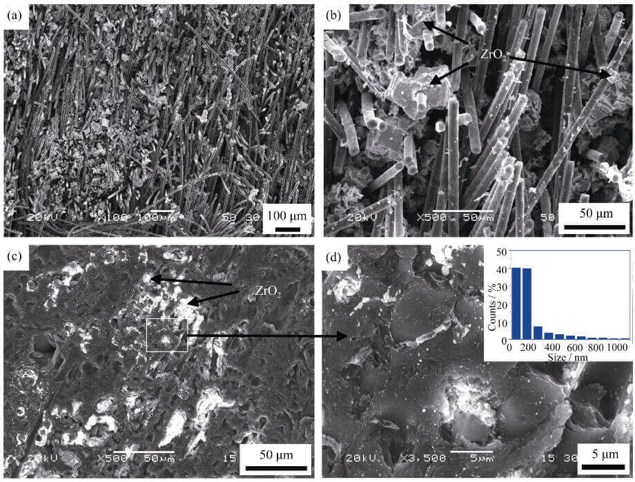
Fig. 2 SEM images of zirconium-containing carbon felt before (a, b) and after (c, d) densification (inset in d showing ZrO2 size distribution) by TCVI process
smaller (small capillary radius) and thus have greater capillary force, and the zirconium oxychloride solution is easy to adhere to these areas. These regions eventually result in ZrO2
The content is high. It can be seen from Fig. 2(c) that the size of these ZrO2 particles is mainly located in the micron scale, however, from the further enlarged photo (Fig. 2(d)), these micron-sized particle aggregates are mainly composed of nano ZrO2 (~40% ) and a small number of micron/submicron size particles, and the content of ZrO2 near the fiber is relatively high.
ΔPmax = 2σ/R(3)
Where ΔPmax-capillary force; σ-liquid surface tension; R-capillary radius.
Figure 3 is the XRD spectrum and SEM microscopic morphology of the C/C-ZrO2 composite material after graphitization. The C/C-ZrO2 composite is mainly composed of C and ZrO2 before graphitization (Figure 1), and after graphitization is mainly composed of C and ZrC (Figure
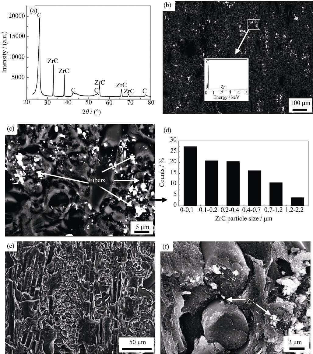
Fig. 3 XRD patterns and morphologies of CC-ZrO2 composites after graphitization
3(a)), and the energy spectrum (Figure 3(b)) also shows There are only two elements, C and Zr, so it can be inferred that the ZrO2 contained in the C/C-ZrO2 composite material has completely changed into ZrC after graphitization, that is, the C/C-ZrO2 composite material has become a C/C-ZrC composite material. Material. From the backscattered electron images (Fig. 3(b, c)), it can be seen that the white ZrC is very easy to distinguish, the distribution of ZrC in the C/C composite is relatively uniform macroscopically, and the content of ZrC near the carbon fiber is higher microscopically. ZrC mainly exists in the form of micron/submicron and nanoscale particles in C/C composites (Fig. 3(d)), which is consistent with the particle size distribution of ZrO2 in C/C composites before graphitization . However, ZrO2 is easy to distinguish from pyrolytic carbon before graphitization (Fig. 2(c)), but ZrC formed from ZrO2 after graphitization is not easy to distinguish from pyrolytic carbon (Fig. 3(e)), only at higher magnification (Figure 3(f)) can be observed, which is mainly caused by the different conductivities of ZrO2 and ZrC.
Figure 4 is a TEM photo of the C/C-ZrC composite. From the low-magnification photos, it can be found that there are many holes between the interface between the carbon fiber and the matrix (Fig. 4(a)). Comparing the SEM photos of the fiber-matrix interface (Fig. 3(f)), it is found that there are pores between the fiber and the matrix, indicating
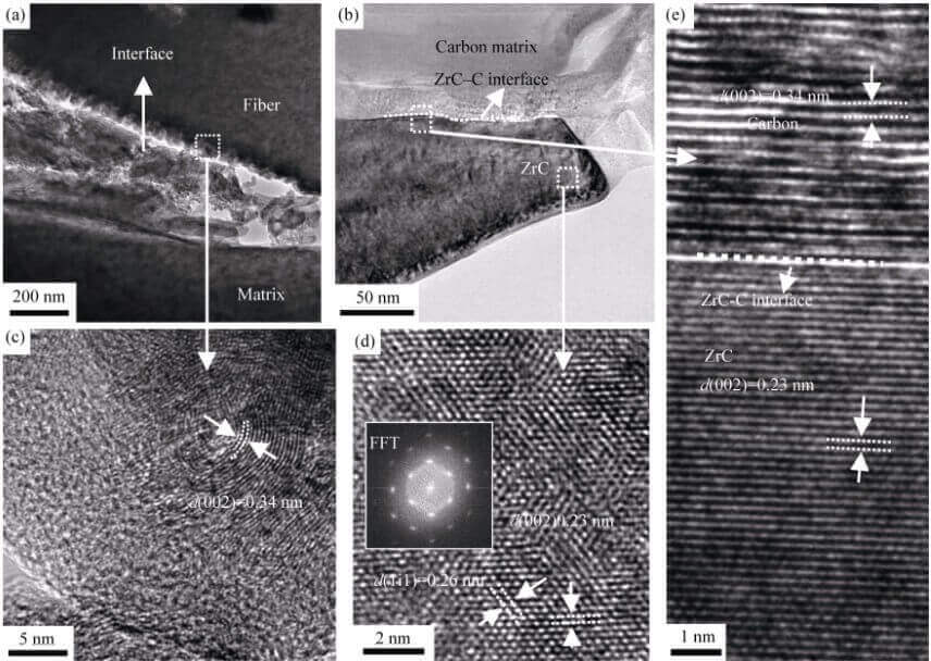
Fig. 4 TEM images of C/C-ZrC composites
(a) Low magnification image of the fiber-matrix interface; (b) Low magnification image of the ZrC-C interface; (c) HRTEM image of the fiber-matrix interface; (d) HRTEM image of ZrC (inset shows the image of Fast Fourier Transformation, FFT); (e) HRTEM image of the ZrC-C interface
that these pores are inherent in the material itself. The high-resolution TEM (HRTEM) images of C/C-ZrC composites further show that although the pores separate the carbon fibers from the matrix, a large amount of pyrolytic carbon is still attached to the surface of the fibers (judged by the ring lattice stripes, Fig. 4(c )), indicating that the pores are formed at the position where the fiber-matrix interface is biased towards the matrix, and there is no porosity between the fiber-matrix interface before the material is graphitized (Fig. 2(d)). The difference in thermal expansion coefficient and high-temperature graphitization generate thermal stress inside the material [19], forming stress concentration at the interface between the fiber and the matrix, resulting in the debonding of the fiber and the matrix at the interface to form pores, thereby releasing the thermal stress [20, 21]. From the low-magnification TEM photo of the interface between ZrC and pyrolytic carbon (Fig. 4(b)), it can be seen that there are no pores or cracks between the interface between ZrC and pyrolytic carbon. (d) and (e)) obtained the lattice structure information of ZrC and pyrolytic carbon, and further confirmed that the ZrC-pyrolytic carbon interface is dense (no porosity), indicating that the ZrO2 and pyrolytic carbon formed by the reaction The ZrC-C interface has good bonding strength.
2.2 Bending properties of C/C-ZrC composites
Figure 5 is the bending load-displacement curve of the C/C-ZrC composite sample. When the displacement is in the range of 0–0.2 mm, the bending load increases linearly with the displacement, then the rate of increase of the bending load decreases
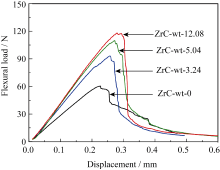
Fig. 5 Typical flexural load vs. displacement curves for CC- ZrC composites
slightly (the slope of the load-displacement curve decreases slightly), and a step-like decline occurs after the load reaches the maximum value. The bending load of the permanent specimen showed an approximately vertical linear drop, showing the characteristics of brittle fracture. For the unmodified sample, the bending load decreases slowly after reaching the maximum value, except for a straight drop at the displacement of 0.25 mm, which generally shows the characteristics of “pseudoplastic” fracture. Moreover, the slope of the linear part of the curve increases correspondingly with the increase of ZrC content, indicating that the introduction of ZrC increases the flexural modulus of the material. At the same time, with the increase of ZrC content, the load-
The area under the displacement curve also increases accordingly (the sample size and test conditions are the same), and the displacement when the material reaches the maximum load also increases correspondingly, indicating that the introduction of ZrC improves the toughness of the material.
The flexural strength, modulus and fracture toughness of C/C-ZrC composites are shown in Table 2. The flexural strength, modulus, and fracture toughness of the unmodified sample were 25.0 MPa, 6.7 GPa, and 17.3 MPa∙ m1/2, respectively, and the flexural strength, modulus, and fracture toughness of the modified material increased with the increase of ZrC content. When the ZrC content is 12.08wt%, its strength, modulus and fracture toughness are 42.5 MPa, 9.6 GPa and 25.6 MPa∙ m1/2, which are 70.0%, 43.3% and 48.0% higher than those of the unmodified sample. .
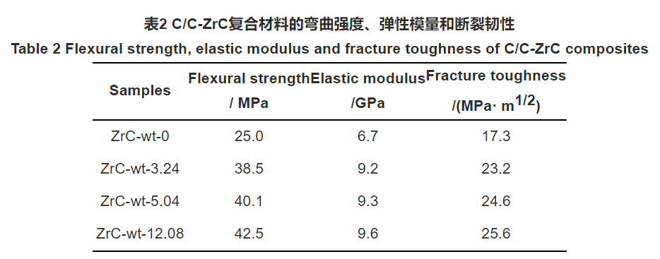
Table 2 Flexural strength, elastic modulus and fracture toughness of CC-ZrC composites
2.3 Bending fracture morphology of C/C-ZrC composites
The fracture process of C/C composites is a process in which cracks are generated inside the material and propagate until they cross the entire sample interface. Crack propagation generally follows two paths: one is along the matrix direction (perpendicular to the fiber direction); the other is along the interface direction (parallel to the fiber axis). The bonding strength of the fiber-matrix interface has a great influence on the final strength of the C/C material. The interface is the bridge connecting the matrix and the fiber, and the force is transmitted to the fiber through the interface matrix. The interfacial bonding strength can be divided into three situations that have different effects on the material strength[22]: (1) The fiber-matrix is a strong interfacial bonding. When the crack propagates along the matrix to the fiber, the crack directly passes through the fiber, and the matrix and the fiber break together. , in this case, the material can reach a higher strength, but the load drops rapidly after the material breaks, which is the phenomenon of brittle fracture; (2) The fiber-matrix is bonded at the weak interface, and the crack propagation will change the original direction when encountering the fiber, It spreads along the matrix-fiber interface, causing the debonding of the fiber and the matrix until the shear failure of the composite occurs. But in this case, the matrix loses the role of transmitting load, the role of the fiber is not fully exerted, and the mechanical properties of the composite material are very low; (3) The fiber-matrix interface is well bonded. When the crack propagates to the fiber, part of the energy is absorbed by the interface. Absorption, causing debonding between the fiber and the matrix, the front of the crack expands forward along the interface direction under the action of stress concentration, and another part of the energy is used for the matrix crack to bypass the carbon fiber and continue to expand along the original direction. After the interface is debonded, as the width of the matrix crack increases, the fiber is gradually pulled out from the matrix, and there is relative sliding between the fiber and the matrix, resulting in frictional shear stress. The longer the length of interfacial debonding (that is, the deeper the crack extends along the interface), the greater the friction between the fiber and the matrix. When the friction exceeds the tensile strength of the carbon fiber, the fiber will break. In this case the material will achieve a higher strength than under strong interfacial bonding.
Fig. 6 is a scanning electron micrograph of the fractured C/C-ZrC composite material. The fracture surface of the unmodified sample (Fig. 6(a)) has the majority of areas where the fibers are flush with the matrix and where the fibers are pulled out longer, indicating that the unmodified C/C composite sample also has strong fibers- Matrix interfacial bonding and moderate (or weak) interfacial bonding. The modified samples (Fig. 6(b-d)) are mainly characterized by fiber pull-out, and there is very little fiber and matrix fracture evenly, and the fiber pull-out length is longer in the fiber-dense area with high ZrC content. , there are ZrC particles attached to the surface of the fiber, indicating that the fiber-matrix interface bonding of the modified material is moderate, and the introduction of ZrC weakens the fiber-matrix interface bonding. Moreover, a large number of zig-zag morphology appeared on the surface of the matrix of the modified sample, which indicates that the crack has a longer propagation path in the carbon matrix, which is conducive to improving the toughness of the material [23].
In order to further study the formation reasons of the interface characteristics of the modified material, the C/C-ZrC composite material was polished with 1000# SiC sandpaper, and the scanning electron microscope photo after grinding is shown in Figure 7. It can be seen that under the shear force of SiC particles in the sample, a large number of loose ZrC particles, pyrolytic carbon fragments and holes appeared in the fiber-intensive area, which is not conducive to the improvement of material strength, while the fiber with ZrC content This phenomenon does not appear in the sparse area, indicating that the fiber-matrix interface bonding is weaker in the fiber-dense area. The reasons are as follows: Thermodynamic calculations [15] show that ZrO2 will react with carbon to form ZrC above 1667 °C. When the temperature reaches this temperature value during the graphitization heating process, ZrO2 and carbon will start to react. At this temperature, ZrC (melting point 3540 °C) and ZrO2 (melting point ~2700°C) are not sintered. Although ZrC has been graphitized at 2500 °C, it has not been sintered due to its high melting point, resulting in weak inter-particle bonding of ZrC powder, so the fiber-matrix interface bonding is weak in the fiber-dense area with high ZrC content. The ZrC-C interface is derived from the interfacial reaction between ZrO2 and pyrolytic carbon, and the ZrO2-C interface is formed by the deposition of gaseous carbon source on the ZrO2 surface, so the ZrC-C interface is a strong/moderate interfacial bonding. Because the carbon matrix is a turbostratic graphite structure, the pyrolytic carbon layer is bonded by van der Waals force instead of covalent bonds in the layer, so the pyrolytic carbon layer bonded by van der Waals force will form layers under the shear force of sandpaper. Cracks (Figure 7) are produced by inter-fracture, and the matrix will produce a zig-zag morphology in the bending test.
The final performance of the composite material is determined by the properties of the fiber, the matrix itself and the bonding strength of the fiber-matrix interface [5]. For continuous fiber-reinforced composites, under the assumption that the fiber and matrix properties remain unchanged, the fiber-matrix interface is properly bonded, and the longer the fiber is pulled out, the better the final performance of the material. Since the C/C composite material and the modified material use the same fiber preform and preparation process, the difference is that the high-strength/high-modulus ZrC ceramic phase is introduced into the modified material matrix. If the introduction of ZrC into C/C composites only weakens the fiber-matrix interface, the strength and toughness of the C/C composites will increase but the modulus will decrease. In fact, the modulus of the material will also increase after the introduction of ZrC. (Table 2), it can be inferred that the increase in the final modulus of the material after the introduction of ZrC should be caused by the increase in the matrix modulus, which also shows that the introduced ZrC is well combined with the matrix (otherwise the introduced ZrC will not work , the modulus will not increase), and if ZrC is well combined with the matrix, it will also lead to an increase in the strength of the matrix, which is consistent with the actual test
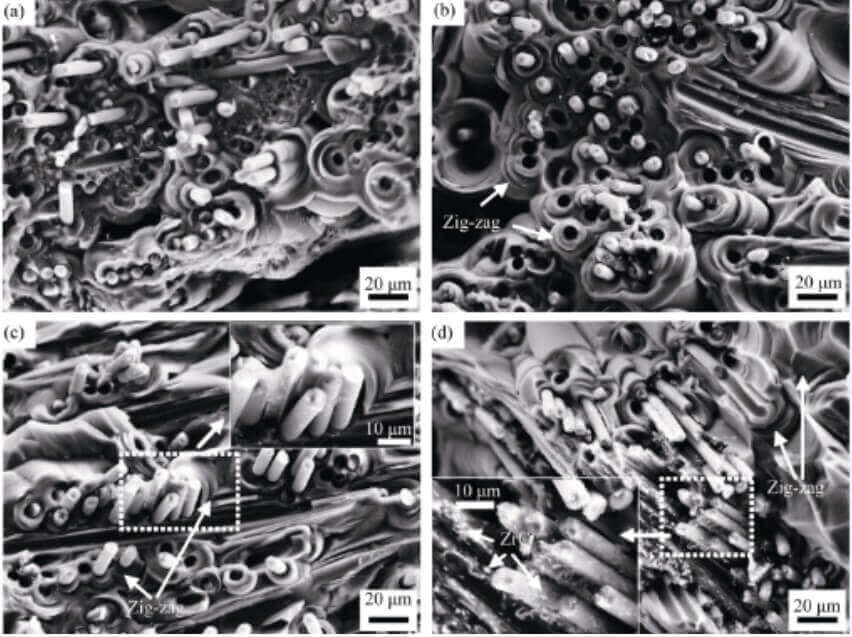
Fig. 6 Fracture morphology of CC-ZrC composites
data. The introduction of the ZrC ceramic phase changes the properties of the matrix and the fiber-matrix interface, and also changes the properties of the fibers. This is because ZrC comes from the reaction between ZrO2 and carbon during the graphitization process, and ZrO2 is inevitably contacted with carbon fibers. Reacts with carbon fibers, resulting in fiber damage and reduced strength. Therefore, according to the measured data and the above analysis results, it is further demonstrated that under the condition of reduced fiber strength, the introduced ZrC has a good combination with the matrix, which improves the matrix strength and modulus, thereby improving the final performance of the composite material.
The research results of the mechanical properties of ceramic matrix composites show that [5]: for granular composites, the strength of the particles should be as high as possible, and the interfacial bonding strength of the granular composites should be increased as much as possible under the premise of ensuring that no penetrating particle damage occurs. The material can achieve better comprehensive
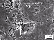
Fig. 7 SEM image of CC-ZrC composites polished by 1000 grit SiC paper
performance; the smaller the particle size, the higher the strength, and the higher the interfacial bonding strength is required. If the interfacial bonding is too weak, for the matrix-based particle composites, the particles are equivalent to defects, and the higher the volume fraction, the more serious the strength decline. The matrix in the C/C-ZrC composite is equivalent to the ZrC particle reinforced carbon matrix composite, and its strength is related to the ZrC particle size and the ZrC-C interface strength. Fig. 8 is the morphology diagram of ZrC in the carbon matrix after bending fracture of the C/C-ZrC composite. It can be seen that nanometer and submicron ZrC particles are embedded in the carbon matrix and protrude from the matrix, and there are no obvious cracks and pores between the ZrC particles and the carbon matrix, indicating that ZrC and pyrolytic carbon are well combined, and the carbon matrix is in the During the fracture process, the fracture along the ZrC-C matrix interface causes crack deflection and prolongs the crack path, which is beneficial to improve the toughness of the matrix; nanometer and submicron ZrC have higher strength and modulus than micron ZrC, Its embedding in the carbon matrix is more conducive to
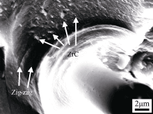
Fig. 8 Morphology of ZrC in the matrix after three-point bending test
improving the strength and modulus of the carbon matrix, which provides further evidence for the improvement of the performance of the carbon matrix reinforced by ZrC; at the same time, the presence of micron-sized ZrC particles in the fiber-dense area (Fig. 7) has a significant impact on the strength of the carbon matrix. is unfavorable, but the strength of the final matrix and the material are improved, indicating that its impact on the final properties of the material is secondary and does not lead to a decrease in the performance of the material.
3 Conclusion
1) ZrOCl2 solution impregnation method was used to introduce zirconium compounds into carbon fiber preforms, and C/C-ZrC composites were prepared through heat treatment, TCVI densification and high-temperature graphitization processes. The flexural properties of the material were tested by the three-point bending method. The flexural strength, modulus and fracture toughness of the unmodified sample were 25.0 MPa, 6.7 GPa and 17.3 MPa∙m1/2, respectively. The flexural strength and modulus of the modified material were The content of ZrC increases with the increase of ZrC content. When the content of ZrC is 12.08wt%, its strength, modulus and fracture toughness are 42.5 MPa, 9.6 GPa and 25.6 MPa∙m1/2, respectively, which are higher than those of unmodified samples. 70.0%, 43.3% and 48.0%.
2) ZrC is embedded in the matrix near the fiber-matrix interface in the form of nano-, sub-micron and micron-sized particles, and combines well with the carbon matrix. In the fiber-dense region with higher ZrC content, the fiber-matrix interfacial bonding is further reduced.
3) The presence of weakly bonded micron-sized ZrC particles is not conducive to the improvement of the matrix strength, but its impact on the final properties of the material is secondary. The existence of submicron/nano-sized ZrC particles in the carbon matrix and good ZrC-C Interfacial bonding increases the strength and modulus of the matrix, which in turn improves the final properties of the composite.
Ablation-resistant materials are mainly divided into three types:
1. C/C composite; carbon fiber composite material,
2. C/SiC: C/C-SiC composite; carbon ceramic composite
3. C/C-ZrC: C/C-ZrC composite;
CFCCARBON CO., LTD is a professional manufacturer of ablation resistant materials, for more details, you can contact us. We need to know the following parameters to judge: heat flow, enthalpy, pressure, temperature, ablation time.
More videos to check the youtube link:
Related news/knowledge:
1.Ceramic matrix composite (CMC) material | professional manufacturer in China
2. Tensile strength of carbon-carbon composites (1)- effect of C/C density
3. Properties of 4D carbon carbon composite | C/C composite material
4. Combustion joining of C/C composites to TiAl- microstructure of the joint