Atomic force microscopy, light microscopy, laser scanning confocal microscopy, scanning electron microscopy and transmission electron microscopy yield complementary information on the complex microstructure of the pyrolytic carbon matrix.
Cells. The infiltrated felt is composed of cells exhibiting sharp cell boundaries, each call containing one carbon fiber and the pyrolytic carbon deposited on this fiber. During ion etching, material is preferentially removed at boundaries between different cells and especially between adjacent HT layers. The observation of trenches at cell boundaries can be interpreted either in terms of a lower material density and reduced structural order or in terms of a different orientation of matrix structural units in relation to the Ar+ ion beam.
Layers. Different surface height levels and surface roughness values after polishing and subsequent additional Ar+ ion etching are associated with differently textured regions.
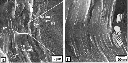
Fig.4-SEM micrographs of the fracture surface of the composite
Elliptical depressions. Depressions are found within the entire HT layer by AFM. The depressions found in the outer HT layer by AFM are not visible in the LSCM maximum intensity image. This indicates that the smaller depressions found by AFM in the inner HT layer also do not result in a contrast in the LSCM maximum intensity image. This means that the contrast observed in the inner HT layer in Fig.2c arises from changes in the reflectivity, i.e. a different local orientation of the carbon layers relative to the polarized light results in a different brightness.
Zig-zag shaped lamellae. SEM images of fractured surfaces show zig-zag shaped lamellae. The thickness of a lamellae lies between about 0.5 um in the inner HT layer and approximately 1 um in the outer HT layer whereas the average distance between sharp bends is about 1 um. These dimensions correlate well with the dimensions of the depressions mentioned above, which are found by AFM.
The varying roughness observed on fracture surfaces might result from different local orientations of carbon layers .The basal planes above the upper and below the lower dashed line are expected to be almost perpendicular to the C/C composite surface whereas the carbon basal planes between the two dashed lines are supposed to be more parallel to the surface. This explanation is in accordance both with TEM observations showing altered Bragg contrast between domains and with the detection of differently oriented small structures in the inner HT layer in LSCM maximum intensity images. These differences in the local orientation of these small structures in the inner HT layer might well result in different etching rates. This, in turn, could explain the AFM observation of depressions within the HT layers.
Columnar grains. Columnar grains could only be observed by using polarized light: by PLM and LSCM. The large columnar grains in the HT layers are not visible in AFM and LSCM topography. However, depressions were observed in AFM topography in the HT layer, which might result from differences in the local orientation of the carbon layers. This may be interpreted as an indirect observation of columnar grains by AFM.