AFM topography after polishing and subsequent ion etching shows that the surface of the MT and HT layers are elevated with respect to the fiber and LT layer.
The root means square surface roughness and differences in topographic height as determined by AFM as a function of the distance to the center of an ion etched C/C composite sample.
Trenches along cell boundaries are found frequently. These trenches are especially pronounced at boundaries between adjacent HT layers. However, no evident etching effect is observed at the boundaries between adjacent differently textured layers within one cell.
Within the area of the HT carbon layers, many elliptical depressions are observed. A zoom-in is shown in Fig.2b. The region shown in Fig.2b is marked by the white square in Fig.2a. Between the MT and the HT layer, a transition zone with a thickness of about 4 um can be recognized. By comparing the layer thicknesses as determined by AFM and PLM this transition zone can be identified as a sublayer of the HT pyrolytic carbon layer. In the following, this sublayer will be called inner HT layer according to the distance to the fiber, the second sublayer will be called outer HT layer. In the inner HT layer the depressions are significantly smaller than in the outer HT layer. The structure of the columnar grains can not be detected by AFM.
The laser scanning confocal microscopy (LSCM) maximum intensity image displayed in Fig.2c was taken using polarized light. The depressions found by AFM in the main part of the HT layer can not be identified in the maximum intensity image of Fig.2c. Instead columnar grains with a typical width of 5 um are visible. In addition, structures are found by LSCM in the inner HT layer that are clearly smaller. Fig 2d shows the topography plot derived from LSCM of the same sample area as shown in Fig.2a. The height differences determined from LSCM are in agreement with the AFM data. The trenches between HT layers belonging to different cells are also visible.
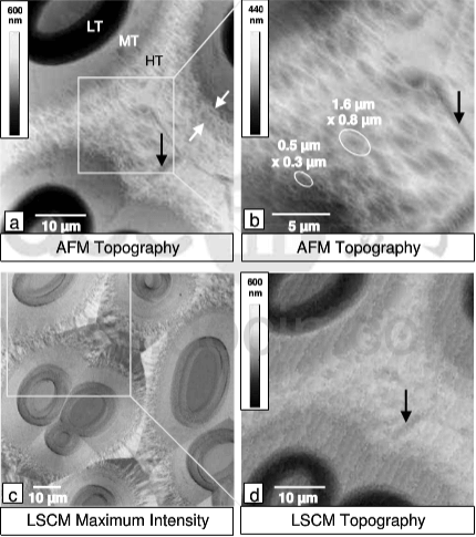
Fig.2(a,b)AFM topography and (c,d) laser scanning confocal microscopy images of an infiltrated carbon felt after ion etching