Test specimens exposed to the three cycles of thermal shock at different peak temperatures are shown in Fig.6(a) to (c). It can be noticed that further oxidation occurred at the exposed lateral surfaces of the C/C composite with increasing number of thermal cycles. For instance, further oxidation at the lateral surfaces of test specimens exposed to 400C and 600C resulted in a reduction of visible voids and cracks, as shown in Fig.6(a) and (b). Nevertheless, the carbon matrix at the surface degraded further by increasing the number of thermal cycles that resulted in the fibers to separate from the surface, as shown in Fig.6(c) for 700C and Fig.7 for 1000C test specimens.
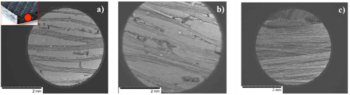
Fig.6-SEM micrograph of 400C, 600C and 700C 2D CC composite test specimens showing surface oxidation
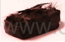
Fig.7-1000C, 2D CC composite test specimen showing fibers separating from the surface
The top surface of test specimens exposed to one cycle thermal shock conditions were next analyzed to identify surface damage due to material degradation. It was observed that at moderate temperatures, i.e., above 600C, carbon located at the surface of the test specimens started oxidizing as the carbon matrix is more susceptible to react with oxygen than the carbon fibers. Matrix cracking and degradation at the surface of the composite increased with increasing the thermal shock peak temperature from 600C to 800C, as shown in Fig.8(a) to (d).
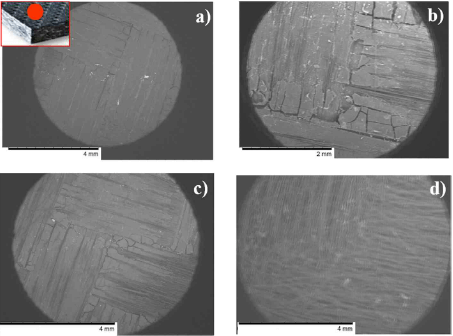
Fig.8-SEM micrograph of top surface of (a)pristine (b)600C (c)700C (d)800C 2D CC composit test specimens showing matrix cracking and degradation
Finally, microstructural analyses at both the interior and the edges right under the exposed surfaces of test specimens exposed to three cycles of thermal shock were performed. Micrographs of polished test specimens displayed more prominent modes of oxidation. By analyzing the interior of test specimens exposed to 400C and
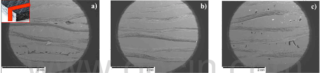
Fig.9-microstructural analysis of the interior of polished 2D CC composite test specimens
700C, the evolution of cracks and voids through the interior of the composite was captured as shown in Fig.9(a) and (c), respectively. On the contrary, fiber tows and matrix within the interior of test specimens exposed to 600C showed lesser oxidation. Following this, the edge of polished test specimens was analyzed by using both, SEM and optical microscope. That is, both micrographs were taken at the same position and they were compared in order to capture most of the oxidation phenomena. It was observed that by increasing the thermal shock peak temperature, exposed fibers became more glossy and sharp as compared to the 400C test specimen. Therefore, it was verified that oxidation attack was maximal for 1000C test specimen since oxidized fibers were excessively misaligned from the tow direction. Also, this behavior corroborates the observation that during the oxidation process the ends of the fibers adopt a “needle-shape”, as discussed before. Further, void/crack growth was manifested for 400C, 700C and 1000C test specimens, as shown in yellow in Fig.10(a), (b), (e), (f) and (g).
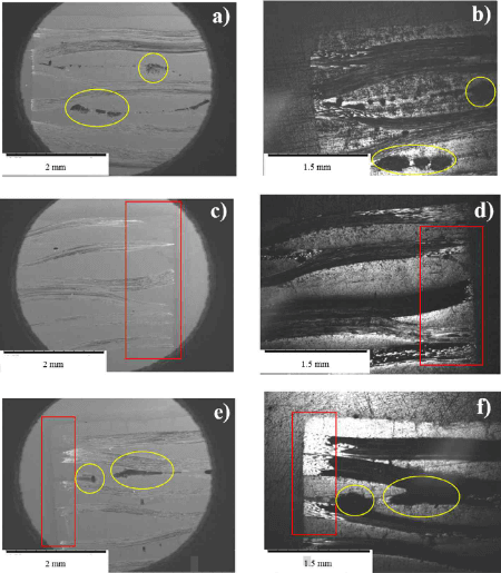
Fig.10-SEM micrograph showing the edge of CC composite test specimens.
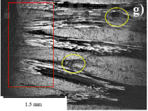
Fig.10(g)-SEM micrograph showing the edge of CC composite test specimens.
Therefore, microstructural examination on test specimens exposed to one cycle and three cycles of thermal shock provided evidence to state that the matrix was more susceptible to degrade than the fibers due its high reactivity. Also, the initiation of significant tow/matrix interface degradation was observed at moderate temperatures. The microstructural analysis also revealed that at low temperatures, i.e. 400C, uniform oxidation attack occurs within the interior of the composite, resulting in good agreement with Bacos. At moderate temperatures, i.e., 600C, oxidation attack was strictly located at the surface of the composite, while the diffusion of gases through the composite was minimal. Thus, it is suggested that chemical reaction was the main mode of oxidation for moderate temperatures. On the contrary, at high temperatures, i.e., above 600C, two oxidation mechanisms were present: First, oxygen reacted with carbon at the surface of the composite, followed by the diffusion of gases through the interior of the composite.