The bearing strength was measured using the tensile bearing method. All specimens had 0.5-inch holes. In the edge-bearing specimens the centers of the holes were placed 0.5 inch from the edge of the specimens. This was to simulate the distance between the outside fasteners and the edge of the radiator panels. In the center-bearing specimens the hole centers were moved to 1.5 inches from the edge to simulate a fastener in the interior of the panel. The specimens were cut in either the 0° or 22.5° direction. At the time the radiator preliminary designs were completed there was a concern that the 22.5° lay-up of the fabric could result in an inadequate level of shear strength near the panel edges. This lack of stregnth would have necessitated applying a doubler to the edge of the actual EO-1 radiator panels. To simulate the presence of a doubler, two panels were sliced in half and bonded back together to give a doubled thickness panel. Unfortunately the glue was applied too thickly and resulted in specimens with too much glue between the C-C plies.

Table IV.-Mechanical test data for 2-ply EO-1 C-C facesheet ad comparable 8-ply material.
The average bearing strength values of the single composites in the 0° and 22.5° directions in both center and edge tests was 12.5 ksi. The average bearing strength values of the double composites in the 0° and 22.5° directions in both center and edge tests averaged 12.1 ksi. All the specimens failed in crushing except for the doubled edge specimens that failed in shear. It appeared that during the test of the doubled edge specimens that the glue layer failed first followed by the C-C composite. It was concluded from the good strength values and the lack of shear failure in the single edge specimens that the doubling of material was not needed in the final radiator composites.
In-plane thermal expansion
The thermal expansion of the specimens was measured in the 0° and 90° directions using an potical interferometry system. The expansion of the specimens was measured between 120°C and -100°C. Over this temperature range the expansion was fairly linear. The coefficient of thermal expansion was calculated using a linear fit of the data between 120°C and -100°C. Figure 6 shows the overlap and linearity of the data. The average CTE in the 0° direction was -1.23*10-6/K and -1.26*10-6/K in the 90° direction.
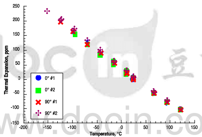
Fig.6-Thermal expansion versus temperature for EO-1 C-C facesheet material.