The working furnace is a heating unit with low thermal inertia. With a working temperature limit of 2150-2200°C the proportion of thermal energy expended in heating graphite equipment and the mass of charge is markedly small compared with thermal energy losses, carried away by water cooling for the metal body of the furnace. The greatest heat loss is in the current leads and in the bottom, which due to the danger of a short circuit for current leads is not thermally insulated to an adequate extent. Calculated heat losses at a working temperature of ~2200°C through the uncovered in the bottom may reach 450 kW/m2. The gas supply, placed in the bottom of the furnace, may carry off through the walls of the graphite cylinder up to 10 kW, due to re-emission within the cylinder of up to 45 kW, and through the graphite support up to 20 kW. Evaluation was carried out for the known level of thermal conductivity of structural graphite grade GMZ, geometric parameters of components and assemblies, and the level of temperature in the workspace and the side bar surface. Each current lead may carry of from the furnace up to 32 kW due to the considerable exposure of the lower graphite crosspieces of the heaters from the working zone, and heaters are joined in pars. The side body of the furnace over the height gives off more than 50% of the total energy consumed. Heat insulation of the side bar is made from lamp black packed in a mesh of graphite cloth. The furnace cover passes up to 20% of the thermal energy released from the furnace. In the furnace cover there considerable liberation through the graphite gas supply due heat release through the wall of the tube and radiation into the inner volume of the gas supply. The actual picture of the thermal condition in the workspace of a furnace leads to a nonuniform thermal condition of product being treated.
Results are shown in Fig.1 for measurement of blank temperature on heating and isothermal soaking for three production operation regimes. As may be seen, in the field of relatively low temperature there is a
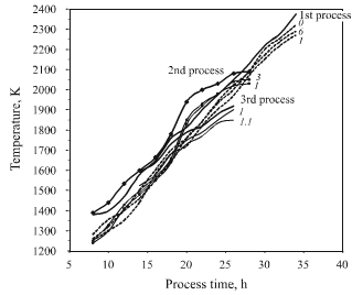
fig.1-furnace graphite surface temps during 3 heat treatment processes
marked delay in heater and blank heating temperature. In the temperature range above 1800K curves are equidistant and converge. As may be seen, the intensity of heat fluxes is proportional to T, K4, and it is so great that temperature control for a charge becomes effective. At the same time, there is a significantly lower level of temperature down a furnace and maximum level in the central part are retained, according to which there is some reduction in temperature in the upper cover. All of this indicates retention of a steady-state heat flux within the volume of a furnace and in the section of blanks being treated in this process. The difference in temperature for blanks at the outer surface is within the limits of 50°C. Between the hot side of a blank and the inner side it is supplemented by up to 50°C, which is considerably greater than the measurement error provided above.
In order to clarify the actual execution of temperature regime in a production process distribution has been determined for the maximum achieved temperature in individual blanks by measuring the thermoeletromotive force of graphite indicator specimens by the procedure described previously in. Here the hot junction of a circuit is on a graphite indicator specimen and a copper plate serves as the cold junction. This procedure makes it possible to determine only the limiting treatment temperature achieved, which corresponds to the achieved level of structural rebuilding of the electron structure of a carbon substance. The indicators were specimens of treated blanks with a previously established prescribed low temperature according a calibration relationship. The calibration relationship in turn was established for heat treatment of original specimens in furnaces with precise control of temperature by an optical method. The measurement error according to the procedure was ±30°C. Indicators were fastened with a carbon thread to blanks, heaters, and the furnace inner wall.