Microhardness: The distribution of Knoop microhardness across the C-C composite/Cu-clad-Mo joints made using Cusil-ABA and Ticusil is shown in Fig.7. Because microhardness tests outcomes are sensitive to the actual measurement path and the distribution of metallurgical phases, multiple hardness scans across each joint were made to confirm the reproducibility and consistency of the data. The hardness profiles of Fig.7 show that fiber ply orientation did not affect the HK distribution either within the Cu-clad Mo region or within the braze region. Additionally, there was no effect of the composite type on the HK values recorded within the braze region. The hardness of the molybdenum substrate is 200-330HK. The hardness of the braze region depends on braze type; Ticusil exhibits a higher hardness than Cusil-ABA. This is consistent with the somewhat greater hardening expected in Ticusil than in Cusil-ABA, and with the somewhat larger residual stresses expected with Ticusil because of its higher liquidus temperature. Additionally, residual stresses due to mismatch of coefficients of thermal expansion can also rather significantly influence the hardness values.
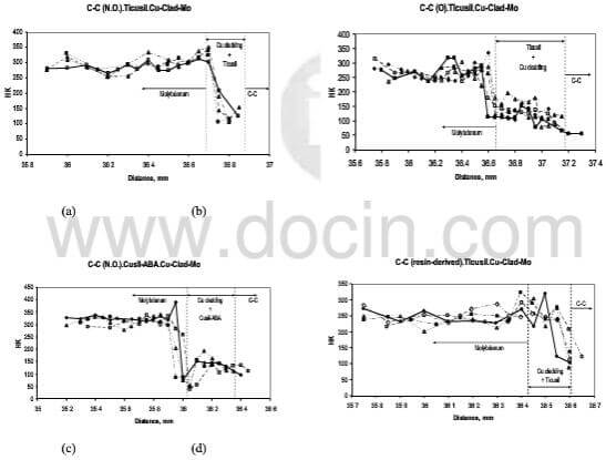
fig.7-knoop hardness distribution across joints
Residual stress at the joint: Upon cooling the brazed joint from an elevated temperature, tensile and shear stresses are induced that weaken the joint and may cause failure. Large residual stresses arising from a mismatch of CTE can appreciably lower the fracture strength of the ceramic. For the C-C/Cu-clad-Mo joints, the CTE of Cu-clad Mo is about 5.6-11.6*10-6/K and the CTE of C-C composite is 2.0-4.0*10-6/K over 20-2500°C. The CTE mismatch between C-C and Cu-clad Mo is, therefore, moderate, and the thermoelastic stresses that develop during brazing and subsequent service may be accommodated without causing joint failure. The CTE of the metallic braze alloys used in our study is very large which will give rise to large elastic thermal strain, △α△T at the braze/composite and braze/Cu-clad Mo interfaces. To understand the effect of residual stresses on the integrity of the joint, simultaneous effects of the plasticity of the braze interlayer and the CTE mismatch between the three materials responding to temperature excursions must be considered.
Analytical and numerial models have been developed to determine the residual stresses at joints between dissimilar materials. For example, Eager and coworkers have developed numerical and analytical models of residual stress relief by metal interlayers taking into account the CTE mismatch and interlayer plasticity. Their models permit estimation of the strain energy in the ceramic for well-bonded ceramic-metal joints. For a small CTE mismatch between the ceramic and the metal substrate, but with a larg CTE mismatch between the ductile interlayer and the base materials, which is the cause with our joints, the elastc strain energy, UeC in the ceramic can be approximated by where
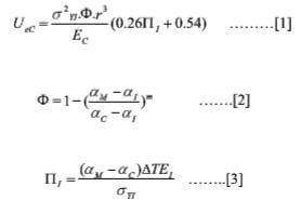
Uec-4
Here, σY1 is yield strength of the interlayer, r is the radial distance from the center of the joint, Ec and E1 arethe elastic modulus of the ceramic and the interlayer, respectively, △T is the temperature change, and α is the CTE of the subscripted phases. The exponent m=1 for α1>(αM+αC)/2, and m=-1 for α1<(αM+αC)/2. Eager et al noted these equations to be accurate to 1% relative to their regorous finite element calculations.
The parameters П1 and Ф in the above equations are dimensionless quantities. The parameter П1 is the ratio of the thermal residual strain at the interface to the yield strain of the braze interlayer; the smaller П1 is, the larger the portion of the interface that remains elastic. The parameter Ф specifies the relative difference in CTE’s between the ceramic, braze interlayer, and metal substrate, and it quantifies the uniformity and symmetry of the residual stress distribution in the interlayer. As Ф approaches zero, the stress distribution in the interlayer becomes more symmetric, which in turn, causes a larger volume of the braze to deform plastically and lower the strain energy in the ceramic, thus reducing the probability of failure from residual stresses.
The strain energy in the C-C/Cu-clad-Mo joints with Ticusil and Cusil-ABA interlayers was computed using the followingproperty data: α1=18.5*10-6/K, αc=3*10-6/K, m=1 for C-C/Ticusil/Cu-clad-Mo joint, Ec=70 Gpa, E1=85 Gpa, △T=887°C, and σY1=292 Mpa. The CTE values of Cu-clad-Mo were obtained as a function of clad layer thickness from the data presented in ref.4; these values vary in the range 5.6*10-6/K to 11.6*10-6/K for clad layer thickness of 0% to 40%. Using the above properties data, the elastic strain energy, UeC=152.98*103.r3 where r is the radial distance in meters. The configuration analyzed by Eager et al is a cylindrical disc-shaped joint whereas out joints are rectangular in cross-section. As a first approximation, we take an effective redius of our joints to be the minimum distance to the edge of our samples. This yields the elastc strain energy in the C-C/Cu-clad-Mo joints in the range of 31-180 mJ, which is roughly of the same order as the UeC of a number of ceramic-metal joints. Considering the fact that the model strictly applies to a cylindrical-shaped joint configuration and monolithic ceramics rather than anisotropic materials such as C-C composites, and the fact that chemical interactions and solute segregation will irrevocably and unpredictably modulate the interphase properties, the calculated strain energy probably representative of the real situation. The fact that there is a relatively large amount of porosity in the virgin 3D C-C composite and that some of the open porosity near the joint interface gets impregnated with the ductile braze during joint formation suggests that some strain relief will be possible within the composite. The absence of fracture in our CVI C-C composite joints is consistent with this observation.