The 3D carbon-carbon composites used in this study were made from P120 carbon fiber and an amorphous CVI carbon matrix, and were obtained from CFCCARBON CORP. These composite substrates were sectioned along two orthogonal directions to expose fiber plies with different fiber arrangements; thus, two sets of composite samples were used for joining: those with oriented fibers at the exposed C-C surface and those with random fibers at the exposed surface. Some joints were made of carbon-carbon composites with T300 fibers and resin-
3D, xyz, CFC, CFRC, CC, carbon, fiber, composites, rods, blocks, tubes, pipes, cylinders, (1)
derived matrix, which were obtained from XXX company. Copper-clad Molybdenum plates from H.C. Starck, inc, were used as the metal substrate. The Cu-to-Mo-to-CU layer thickness ratio was 13%-74%-13%. The Cu-Mo-Cu laminate was manufactured by rolling a Mo core sandwiched between two Cu layers. THe material combines the high conductivity of Cu with the low coefficient of thermal expansion of Mo; the CTE of the clad material is tailored by changing the clad ratio of Cu-Mo-Cu. The commercial brazes, Cusil-ABA and Ticusil, were in powder form and obtained from Morgan Ceramics. THe composites, liquidus and solidus temperatures, and selected physical and mechanical properties of the braze alloys are given in Table Ⅰ.
The composite panels and Cu-clad Mo plates were sliced into 2.54cm*1.25cm*0.25cm pieces. All materials were ultrasonically cleaned in acetone for 15 min. prior to brazing. The braze powders were mixed with glycerin to create a thick paste with dough-like consistency, and applied manually to the C-C surface using a spatula. The Cu-clad-Mo plate was laid over the braze layer and a load of 0.30-0.4 N was applied to the assembly. The assembly was placed in a vacuum furnace with the composite on top and Cu-clad-Mo at the bottom. The samples were heated to the brazing temperature under vacuum isothermally held for 5 min. at the brazing temperature, then slowly cooled to 400°C followed by furnace cooling to room temperature.
The brazed joints were mounted in epoxy, ground and polished, and examined using optical microscopy, and Field Emission scanning microscopy coupled with energy dispersive x-ray spectroscopy. Microhardness scans were made with a Knoop indenter across the joint interfaces on a Struers Duramin-A300 under a load of 200g and loading time of 10 s. To check the reproducibility of the hardness profiles, multiple scans were made across each joint.
Prior to actual joining, a preliminary screening of braze spreading behavior was undertaken on the two types of C-C composite substrates: P120C fiber in a CVI-carbon matrix, and T300 fiber in a resin-derived carbon matrix. This was done mainly because wettability data on C-C composite substrates containing different types of carbon fibers and carbon matrices are scarce although there
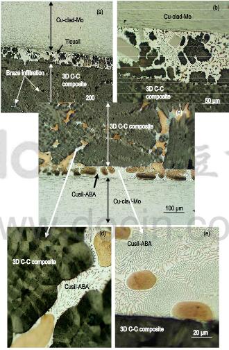
Fig.2-photomicrographs of 3D C-C composite joined to Cu-clad-Mo
is considerable data in the literature on wettability of Ag-Cu-Ti alloys on monolithic carbon substrates. Only a qualitative assessment of the spreading behavior was attempted, and the actual measurements of contact angles were not done. Figure 1 shows the photographs at the conclusion of the solidification of Cusil-ABA and Ticusil braze droplets equilibrated on the substrates at 813°C and 915°C, respectively, after 5 min. contact with the C-C substrates. Both braze alloys displayed good spreading on the C-C substrates, with Ticusil exhibiting a somewhat better surface coverage than CUsil-ABA. This is believed to be due to the higher Ti content of Ticusil than Cusil-ABA, which should enhance the reactive wetting. In fact, both pure Ag and Cu make large contact angles, 0 on carbon, and both metals have large surface tension, σ1v which indicates that these metals in a pure state do not wet carbon. Titanium additions to Ag and Cu markedly and rapidly decrease the 0.
The microstructures of the composite/braze interface and braze/Cu-clad-Mo interface in Cu clad Mo/C-C composite joints are shown in Fig.2. Both Cusil-ABA and Ticusil have infiltrated the inter-fiber regions in the 3D C-C composite. There was no effect of fiber ply orientation at the mating surface on the extent of infiltration. Large-scale counter-gravitational infiltration has occurred during the short brazing time of 5min. because of good wettability. Low-magnification optical views suggest that infiltration distance is on the order of several hundred imcrometers within the C-C composite. This is significant because the carbide forming reactions did not choke the metal flow or limit the extent of braze infiltration. The Tic reaction layer that forms via the reaction Ti+C→TiC is known to be discontinuous with a non-homogenous structure; this permits extensive infiltration of porous carbon by the melt even in short time interval of 5min. This behavior is in contrast to the behavior exhibited by Cu-Cr melts on porous carbon where a dense chromium carbide layer forms and chokes the metal flow, thereby severely limiting the infiltration in spite of excellent wettability. Our observations of extensive infiltration of Ti-bearing Ag-Cu braze alloys in the C-C composites are consitent with the sessile-drop wettability test results of Sobczak et al on Cu-Ti/carbon system.