In order to clarify the actual execution of temperature regime in a production process distribution has been determined for the maximum achieved temperature in individual blanks by measuring the thermoelectromotive force of graphite indicator specimens by the procedure described previously in [9]. Here the hot junction of a circuit is on a graphite indicator specimen and a copper plate serves as the cold junction. This procedure makes it possible to determine only the limiting treatment temperature achieved, which corresponds to the achieved level of structural rebuilding of the electron structure of a carbon substance. The indicators were specimens of treated blanks with a previously established prescribed low temperature according a calibration relationship. The calibration relationship in turn was established for heat treatment of original specimens in furnaces with precise control of temperature by an optical method. The measurement error according to the procedure was ±30C. Indicators were fastened with a CC composite thread to blanks, heaters, and the furnace inner wall. Results obtained are presented in Fig.2. On the whole they correspond to measurements of temperature directly in a furnace. The number of tests in this study may be much greater. It follows from the data obtained that for treated blanks the radiating and heating surfaces are both heaters and the re-emission furnace of the furnace inner wall. The required value of treatment temperature for a charge may only be provided in some single area for product location. In rest of the areas the level of temperature in relation to internal heat flows is distorted and does not correspond to the requirements for the production process. The amount of non-conformity may reach 70-80C, which is markedly greater than the error of optical measurements. The first level for location of blanks as noted above is raised by the graphite stand by 600 mm above the hearth of the workspace. Therefore the minimum temperature for a charge is established for the upper section of blanks. Location of a heat screen at the upper level may apparently lead to considerable equalizing of charge temperature. Temperatures established at the inner surfaces of blanks are not provided in Fig. 2. They are 40-50 degrees less than the temperature of the outer surfaces. Blanks being treated, participating in redistribution of heat fluxes, become re-emitters within a furnace with establishment of a steady-state direction for thermal energy flow. It follows from data in Figs.1 and 2 that in large electric vacuum furnaces the actual treatment temperature achieved for blank is material is with an error up to 100C, which is greater than the error of optical measurements.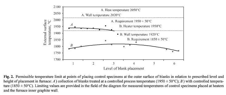
In order to study the permissibility of the HTT production operations noted, a study was made of
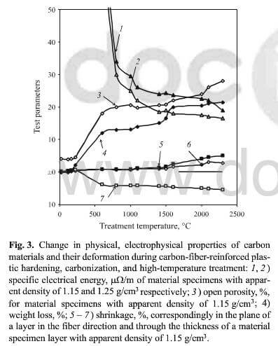
change in physical, electrophysical properties of carbon materials and their deformation during carbon-fiber-reinforced plastic hardening, carbonization, and high-temperature treatment.
physicomechanical and thermophysical properties of treated blank materials. Results are shown in Fig.3 for testing physical, electrophysical, and deformation properties of CCCM during carbon-reinforced plastic hardening, carbonization, and HTT. The reinforcing filler carbon, i.e., carbon fiber, has a higher original high-temperature production treatment, and therefore it is stable over the whole test temperature range. Features presented that occur in material in all stages of the production process of physicomechanical and structural processes reflect the rate, depth, and completion of conversion within polymer and then in a carbon matrix.
It is possible to separate three regions from the data in Fig.3 in the HTT temperature range. With a temperature of 800 to ~1273C shrinkage and weight loss are stabilized, and there is formation of a carbon turbostratic 2D crystal structure, and a change-over is observed towards with respect to the level of electrical conductivity, typical for carbon material. The specific electrical conductivity for carbon materials, as is well known, depends on their porosity and degree of perfection of the crystal an electron submolecular structure of coke.