The properties of carbon carbon composite are not well publicized. For structural applications, the goal is to produce carbon-carbon composite having a density level of 1.8-2.0 g/cc. Increased density calls for a careful selection of yarn bundle size and fiber architecture. A fine weave is more desirable in obtaining high density, although an interconnected, three-dimensional fiber network is preferred for a chemical vapor deposition (CVD) system. As the density of the composite increases, strength and modulus are expected to increase as well. Because of the low strength of the carbon matrix (less than 40Mpa) and weak interface between the fiber and matrix, one of the key issues in the area of CC composite is the improvement of composite through-the-thickness strength. For structural applications, most reinforcement preforms are 3D fabrics.
The mechanical properties of textile-reinforced composites can be predicted with a knowledge of the fiber properties, matrix properties, and the fiber architecture through a modified laminate theory approach. Geometric unit cells defining the fabric structure can be identified and quantified to from a basis for the analysis. For 2D woven fabric-reinforced composites, Dow et al. and Yang et al. have developed models for the thermo-mechanical properties of plain-, twill-, and satin-reinforced composites. Examples of these include the mosaic, crimp, and bridging models developed by Yang et al. In the mosaic model, fiber continuity is ignored and the composite is treated as an assembly of cross-ply elements. With the crimp model, the nonlinear crimp geometry and the yarn segment is treated as a laminae. Although the crimp model was found to be suitable for plain weave composites, the bridging model was found to be best for satin weave composites because it takes relative stiffness contribution of the linear and nonlinear yarn segments into consideration.
The modeling of 3D fiber-reinforced composites also begins with the establishment of geometric unit cells. A summary of the four major classes of 3D fiber architecture is given in figure 25. Three basic yarn components
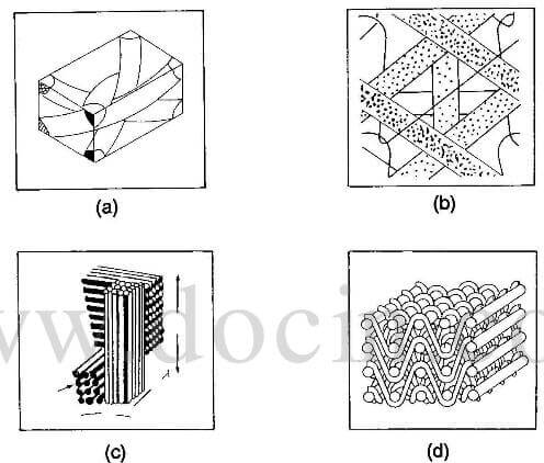
unit cell geometry of 3D fabrics
make up the unit cell for a 3D orthogonal nonwoven fabric, defined according to the yarn orientation: 0°(warp), 90° (weft), the through-the-thickness. Five basic yarn components make up the unit cell for a general MWK fabric, defined according to the yarn orientation: 0°(warp), 90° (weft), 45 °(biss), -45° (bias), and the stitching yarn (through thickness). The fractional volume of fiber in each of the direction can be calculated geometrically on the basis of yarn size, yarn spacing, and stitch construction that should reflect a combination of the orthogonal unit cell and crimp geometry. Several yarns running parallel to the body diagonal of the cell represent the unit cell for the 3D braid. However, in some instances, yarns are placed in longitudinal and transverse directions of the fabric and are referred to respectively as longitudinal and transverse reinforcements.
Among the 3D composites, the 3D braided composites have received much attention because of their improved stiffness and strength in the thickness direction, their delamination-free characteristics, and their near-net shape manufacturing capabilities. Several analytic models have been developed to characterize the elastic modulus and structural behavior of 3D braided composites.
From the preform processing science aspect, Ko et al. developed a fabric geometric model (FGM) based on the unit cell geometry. The stiffness of a 3D braided composite was considered to be the sum of stiffnesses of all its laminae. The unique feature of the FGM is its ability to handle 3D braid and other multidirectional reinforcements including 5D, 6D, and 7D fabrics with straight or curvilinear yarns. The product of the FGM is a stiffness matrix that provides a link between applied strains and the corresponding stress responses. With a properly selected failure criterion, the stress-strain relationship of the fiber-reinforced composite can be predicted.
With the FGM, one can also examine the elastic response of various 3D reinforced composites. For a carbon-carbon
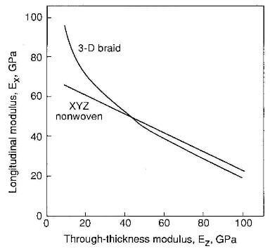
relationship between longitudinal modulus nad through-thickness modulus of 3D composites.
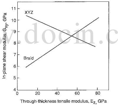
relationship between inplane shear modulus and through-thickness modulus of 3D composites
composite system with 50% fiber volume fraction, the uniaxial tensile modulus Ex, through-the-thickness modulus Ez, and in-plane shear modulus Gxy of an XYZ orthogonal fabric, and a 3D braid reinforced composite are examined. These two reinforcement systems represent the extreme case of linear and curvilinear reinforcement systems as illustrated in the unit cell structures. Assuming equal distribution of fibers in the X and Y directions for the orthogonal fabrics and a 1- by 1-braided structure, figure 28 shows that Ez increases as Ex decreases for both composites. The curvilinear system has high tensile modulus at low values of Ez. At higher tensile modulus values, however, the behavior of both reinforcement systems is similar. On the other hand, figure 29 shows opposite trends of the relationship between Gxy and Ez for the linear and curvilinear reinforcement systems. For the curvilinear system, Gxy increased as Ez increases. This increase reflects the respective sensitivity of the linear and curvilinear-reinforced systems to fiber volume fraction distribution and fiber orientation.